Setting up a Wi-Fi router TP-LINK TL-WR940N and TL-WR941ND. Instructions for connecting and setting up Wi-Fi
The wr941nd router is a modern representative of the N series wireless router line from Tp-link.
This article will focus on versions V5 and below with data transfer rates up to 300 Mbps, but do not forget that version V6 - the latest of the currently released in this model range - already provides speeds of 450 Mbps.
A brief overview of the tp link tl wr941nd router
So, the tp link tl wr941nd router is an ideal choice for creating a high-quality home and small corporate network. Specifications for a fairly low price - and it varies on average from 2,500 to 3,000 rubles - are worthy of special praise.
So, the main technical characteristics of the router are presented in the following illustrations:


Like most Tp-Link models, the design of the router is made in white. The router is equipped with three signal receiving / transmitting antennas, which allows you to cover a greater distance, getting the most out of the equipment's capabilities.
On the front side of the case there is an indicator panel consisting of nine elements:
- "PWR" - informs about the presence of power supply to the router;
- "SYS" - system information: if the indicator is inactive - a system error has occurred, blinking - the system is working correctly;
- "WLAN" - informs about the operation of the wireless network;
- "LAN 1-4" - state of connection and activity of network devices;
- "WAN" - state and connection of the line of the Internet service provider;
- "QSS" - connecting devices to a wireless network using ( when the indicator blinks slowly, the mobile devices are connected to the network, when the indicator blinks quickly, the connection failed).
On the front panel there is also a button to enable / disable the "QSS" function, which is analogous to "WPS".
On the back panel of the tp link tl wr941nd router there are ports and connection connectors:

- "Power" - used to connect the power adapter;
- "Reset" - this button resets to factory settings;
- "WAN" - used to connect the provider's cable;
- "LAN 4-1" - for connecting network devices.
Installing and connecting the tp link tl wr941nd router
When installing a router, you should also consider external factors:
- must be well ventilated;
- the router should be away from heating elements, heating radiators, etc.;
- The router must not be exposed to direct sunlight.
The connection itself is carried out according to the standard scheme:
- connect the Internet cable provided by the provider to the “WAN” port on the router;
- "LAN" through the corresponding ports;
- connect the power adapter to the appropriate socket and plug it into the network.

How to set up internet connection on tp link wr941nd router?
To enter the router interface, use the address 192.168.1.1, which must be specified in the address bar of any Internet browser (by default, login and password are admin).

It is also worthwhile to prepare an agreement with the provider for the provision of Internet services in advance, where you can see the authorization data and the required settings for the router.
Now you can proceed directly to creating a new Internet connection.
To do this, open the "Network" menu, the "WAN" section.

In the "Connection type" line, select one of the options according to your contract:
dynamic ip address

With this choice, all other parameters remain unchanged.
static ip address
Here you just need to specify the "IP address", "Subnet mask" and "Default gateway" provided by your provider.
PPPoE/Russia PPPoE

This is the most "popular" type of connection. Specify in the lines "Username" and "Password" (duplicate in the line "Repeat password") the authorization data according to your agreement.

Fill in the rest of the parameters as needed.
Bigpond cable

For this type of connection, you must specify:
- "Username" and "Password";
- "Authentication Server";
- "Authentication domain".
L2TP/ Russia L2TP or PPTP/ Russia PPTP

In addition to the login and password, when choosing "Statistically ip", you will need to specify the data from the contract (similar to the connection type of the same name).

To complete the configuration of the tp link tl wr941nd router, click "Save".
tl wr941nd router: wifi setup
The wireless mode is configured in the menu section of the same name:

- in the first line "Network name" - specify the name of the network to be created;
- "Channel" - the most important mode in a wireless network: you can leave it in the "Auto" value - for automatic detection, but if you know, you can select it manually (in Russia, from 1 to 13 are used);
- the following parameters can be left unchanged or you can specify the required values as desired.


Here, select one of the provided encryption methods:
a). "WEP" - the method is based on the "IEEE 802.11" standard.

"WEP Key Format" can be either "Hexadecimal" (in the format 0-9, a-f, A-F) or "ASCII" (combination of keyboard characters)
Fill in one of the lines "WEP key" and in the column "Key type" select "64-bit", "128-bit" or "152-bit".
b). "WPA / WPA2" - works on the basis of the Radius server.

- in the "Version" and "Encryption" lines, select "Automatic";
- "IP address of the Radius server";
- "Radius-port" - the port can be left by default;
- Radius server password.
in). WPA-PSK/WPA2-PSK.

By analogy with the previous methods, enter the password in the "PSK Password" line.
To complete the wifi network setup, click "Save".
Setting up IPTV
Setting up IPTV is somewhat more complicated: the fact is that not all hardware versions of the WR941ND router support this technology.
Only the V5 version with firmware "TL-WR941ND_V5_130509_RU" is equipped with "IGMP Proxy", "Bridge" and "802.1Q TAG VLAN" support. Version V3 with firmware "TLWR941ND_V3_121224_RU" has "IGMP Proxy" support.
A complete list of TP-Link products with Multicast/IPTV support can be found on the official website: http://www.tp-linkru.com/article/?faqid=518
To configure IPTV, you only need to go to the "Network" menu - the "IPTV" or "Bridge" section and specify the port number to which the set-top box is connected.
Additional features of the wifi router tp link wr941nd
It is also worth paying attention to the “QSS” technology: to activate and make settings for adding devices, open the “QSS Function” menu and click on the “Enable” button in the first line.

Devices can be added in several ways:
I). With "PBC" (push button):
First option:
Press and hold the "QSS" button (located next to the indicator panel) for 2-3 seconds.
The QSS Service window will appear - click Finish.

Second option:
- press the "QSS" button;
- in the "QSS Service" window, select "Press the button on my access point".

II). By entering a pin code:
In the "QSS function" section, click on the "Add device" button.

In the window that opens, in the line "Enter the PIN code of the new device", enter the pin code - it is indicated in the previous step in the line "Current pin code".

In the "QSS Service" window, select the second line "Enter a PIN code into my access point or registrar" and click "Next".

Thus, the WR941ND router is a worthy representative of the line of public routers with a clear interface and excellent characteristics, it ensures the creation and maintenance of a high-quality network.
Front Panel
INDICATOR |
CONDITION |
MEANING |
Meals included |
||
Power off |
||
The device is booting or a system error has occurred. |
||
The device is working properly. |
||
System error. |
||
Wireless broadcast is disabled. |
||
Wireless broadcast is on. |
||
|
wan, |
There are no devices connected to the port. |
|
A device is connected to the port, but it is not active. |
||
A device is connected to the port and it is active. |
||
Flashing slowly |
The wireless device connects to the network through the WPS function. This process takes approximately two minutes. |
|
The wireless device has been successfully connected to the network using the WPS function. |
||
Fast |
Failed to connect the wireless device to the network using the WPS function. |
Back panel
The following items are located on the rear panel (from left to right).
1,2,3,4 (LAN):
These ports (1,2,3,4) are used to connect the router to computers on the local network.
WAN:
The WAN port is used to connect the Ethernet network.
WPS/RESET:
This button is used to enable WPS and to reset the router settings. To enable/disable WPS, simply press this button without holding it for more than five seconds; to RESET the settings, press the button for more than five seconds.
ON/OFF:
Power on/off.
POWER:
Connector for power supply. Use the power adapter included with the TL-WR941ND/TL-WR940N wireless router.
Wireless Antennas:
are used to receive and transmit data over a wireless connection.
Router connection
- Choose a suitable location for the router. It is recommended to place the router in the center of the wireless network.
- Adjust the position of the antenna. Most often, the vertical position is best.
- Connect the computer to the local network through the LAN ports of the router (if you already have a wireless network adapter and if you want to use the wireless network connection, you can skip this step)
- Connect the incoming Ethernet cable to the router's WAN port
- Connect the power adapter to the appropriate socket on the router, and plug the other end into a power outlet. Turn on the router by pressing the ON/OFF button.
- In your computer's TCP/IP protocol settings, select Obtain an IP address automatically.
To access the router settings, open a web browser and enter the default address http://192.168.0.1 in the browser's address bar.
A login window similar to the one shown in the image below will appear. In the User and Password field, enter admin, using lower case. Then press the button OK or key Enter.
Router setup
After entering the Login and Password, the main Status window and the router configuration menu will open. Equipment can be configured in two ways: Fast and Individual setting.Quick Setup
To carry out quick setup, select the item in the Main menu. Quick Setup
This will open a dialog box that allows you to select the required connection options. In the first window, select Further.
After that, a window will appear with a choice of the type of your connection. The router supports the five most common Internet connection methods - Dynamic IP, Static IP, PPPoE, L2TP, and PPTP. 
When choosing a connection type Dynamic IP you will be taken directly to the Wireless settings page.
When choosing a connection type Static IP address, the following window will be displayed 
The settings to be entered in the corresponding fields are provided by the provider.
IP address– This is the WAN IP address that is visible to outside users on the Internet (including your ISP). Enter an IP address in this field.
Subnet mask– The subnet mask used by the WAN IP address.
Main gate– If necessary, enter the IP address.
Primary DNS Server– If necessary, enter the IP address of the DNS server.
Secondary DNS Server– If you received a different DNS server address from your ISP, enter it in this field.
When choosing a connection type PPPoE, the following window will be displayed 
Username: Password– Specify Username and Password received from your ISP. These fields are case sensitive.
Confirm password - Re-enter the password you received from your ISP to make sure the password you entered is correct. If the password differs from the value entered when confirming the password, a window will appear in which it will be written that the password does not match the previously entered one.
Dynamic IP– Use the dynamic IP address provided by your ISP to connect to the local network.
After pressing the button FURTHER A window with wireless network settings will appear. 
Wireless Broadcasting– By selecting the appropriate item from the drop-down menu, you can enable/disable the function.
Wireless network name– Enter a value up to 32 characters long. The default SSID is TP-LINK_XXXXXX (XXXXXX are the last six unique characters of the router's MAC address). This field is case sensitive. For example, TEST and test are different meanings.
Region– Select a value from the Russia drop-down list.
Mode– Router's wireless transmission mode. Allows you to select the broadcast standard b, g, n or mixed. The optimal setting is mixed mode, because it allows you to automatically connect to any device, regardless of the broadcast standard (device).
Channel Width– Select the appropriate value from the drop-down list. Default value Auto at which the device automatically adjusts the channel width for clients (it is better not to change).
Channel– This field specifies the operating frequency to be used. Default value Auto so the access point will select the appropriate channel automatically. It is not necessary to change the wireless connection channel.
Disable protection– The security function can be enabled or disabled. When this function is disabled, wireless stations can connect to the router without encryption (no password - the network is not secure). We strongly recommend that you select one of the security options.
WPA-PSK/WPA2-PSK– WPA selection based on PSK password.
PSK password– You can use format characters ASCII or Hexadecimal symbols
When choosing ASCII The key can contain numbers from 0 to 9 and letters from A to Z and must be between 8 and 63 characters long. When choosing Hexadecimal, the key can consist of numbers from 0 to 9 and letters from A to F, and its length must be between 8 and 64 characters. Note that the key is case sensitive. This means that the use of uppercase and lowercase letters affects its meaning. You should write down the key and other wireless security settings somewhere.
Without changes– If this option is selected, the wireless data configuration will remain unchanged!
Pushing a button Further, You will be in the window Completion. Click the button To complete to complete Quick Setup. 
The router is configured and ready to go.
CUSTOMIZING YOUR ROUTER
After successfully logging into the router, you will see fifteen main menus on the left side of the web utility. The right side contains background information and instructions. 
First menu item CONDITION. It displays general information about the status of the device. The information in this window is read-only and cannot be edited. 
To individually configure the router, select the item in the menu NET, and in the pop-up menu select the section WAN.

By choosing Network - WAN you can configure the network settings.
Configuring DHCP
If you are using DHCP IP address acquisition (obtain settings automatically), select Dynamic IP, and the router will automatically obtain the IP parameters.
This window shows how WAN settings, including IP address, subnet mask, default gateway, and so on, are dynamically assigned by your ISP. To update the settings, click the button Refresh. To reset the values, use the button Release.
MTU Size– Usually the value MTU(maximum packet size) for most Ethernet networks is 1500 bytes. We recommend that you do not change this value.
Primary DNS and Secondary DNS assigned automatically. You do not need to use this function when assigning IP addresses dynamically.
Node name- This option allows you to assign a hostname to the router (not used on your network).
Obtain an IP address using Unicast DHCP– Some ISP's DHCP servers do not support broadcast applications (this option is not available on your network).
Click the button Save to save the settings.
Setting up a PPOE connection
If you are using a connection via the PPPoE protocol, then you should select the WAN option: PPPoE/Russia PPPoE. 
When setting up a connection via PPPoE, you must specify the following parameters:
Username: Password– Specify the username and password received from the provider from the provider. These fields are case sensitive.
Secondary connection– In this field, you must select the connection type Dynamic IP.
Connection modeWAN- In this section, you must select the item Connect automatically ( If the connection fails, it will automatically reconnect.)
After selecting the options on this page, you must click the button Save.
Setting up a wireless connection
On the menu Wireless mode need to choose Wireless settings. 
This menu item is used for basic parameter setting. 
Network name– In this item, you must enter the name of your network to which you will connect. Specify a value up to 32 characters long. The default SSID is TP-LINK_XXXXXX (XXXXXX is the last six unique characters of the router's MAC address). This field is case sensitive. For example, TEST and test are DIFFERENT meanings.
Region- At this point, you must select Russia.
Mode– Select mode 11bgn mixed. This mode allows all 802.11b, 802.11g and 802.11n wireless stations to connect to the router.
Channel Width– Select channel width Automatically.
Channel- This field sets the operating frequency that you are going to use. The default mode is auto, thus, the access point will automatically select the most suitable channel automatically .
This setting should be left in Auto.
Maximum transfer rate (Tx)- In this field, you can limit the maximum data transfer rate of the router (Tx).
Enable wireless broadcast– The wireless mode of the router can be enabled or disabled to allow access by wireless stations. The wireless broadcast can be turned on/off using the WIFI ON/OFF button on the router. By default, this item should be enabled.
Enable SSID Broadcast- When wireless clients search for the wireless network they want to connect to, they will see the SSID (network name) sent by the router. If you check the box Enable SSID Broadcast, the wireless router will openly broadcast its name (SSID). If the checkbox is not checked, then the name of the network will not be displayed in the list of networks, and in order to connect, it will be necessary to manually enter the network parameters for connection.
WDS- This field must be disabled (empty).
Click the button Save to apply your settings.
Configuring Wireless Network Security
Selecting from the menu Wireless mode- Wireless security, you can configure the security settings for your wireless network.

Disable protection– If you do not want to use wireless network security, click the corresponding item. In this case, your network will not be protected and it will be possible to connect any WiFi device without a password. (Not recommended)
Version– You must select the version of the WPA-PSK encryption algorithm from the drop-down list. The optimal mode is the type WPA-PSK(WPA pre-shared key).
Encryption- When choosing WPA-PSK or WPA You can specify one of the following values as the Authentication Type: TKIP or AES as an encryption algorithm. ( Not recommended enable encryption type TKIP, because this encryption is not supported by the 802.11n broadcast standard). In this setting item, you must select the standard AES.
Wireless network password– Here you can specify a password from 8 to 63 characters in ASCII encoding (that is, it is permissible to use letters and numbers of the Latin alphabet, uppercase and lowercase).
Group key renewal period– This field must be set to 0.
This completes your router setup and is ready to go.
5.3.1 Configuration database (SETUP-DB)
Units of measurement (0; 1; 2). 0 – [Gcal and kgf/cm2]; 1 - [GJ and MPa]; 2 - .
Consumption scheme number (0…99). The scheme is selected, guided by section 4 of this manual. This parameter must be set before assigning other input parameters, since the nomenclature of the database parameters depends on the selected schema. If the change in the SP was made when the account was started, then the parameters V, M, Q, Ti accumulated since the beginning of the current hour will be reset to zero. If it is necessary to save the accumulated data, stop the account, wait until the end of the hour, then change the scheme number and start the account again.
Countdown time. Used to set the internal clock of the heat meter. Specified in hours-minutes-seconds format. The range for setting hours is from 00 to 23, minutes from 00 to 59, seconds from 00 to 59. Changing the reference time, as well as the reference date, leads to a change in the natural order of archiving.
Count date. Used to set the heat meter calendar. Specified in the format day-month-year; the range of setting the day is from 01 to 31, the month is from 01 to 12, the year is from 00 to 99. Changing this parameter entails a change in the natural order of archiving.
Estimated days. Specifies the end date of monthly archiving intervals. Set in the range from 01 to 28 days.
Estimated hour. Specifies the end time of daily and monthly archiving intervals. It is set in the range 00...23 h.
Type of connected temperature sensors. 0 - 100P according to GOST 6651-94; 1 - Pt100; 2 - 100M according to GOST 6651-94; 3 - 100P according to GOST R 8.625-2006 or according to GOST 6651-2009; 4 - 100M according to GOST R 8.625-2006. They choose, guided by the marking of the vehicle in his passport. Only the same type of resistance thermometers may be used.
Flow control (0; 1; 2; 3). The parameter sets the rule for the operation of the device when the current flow rates G1, G2, G3 go beyond the boundaries of the ranges, respectively, Gн1…Gv1, Gн2…Gv2 and Gн3…Gv3
– at KG = 0 – NS activation:
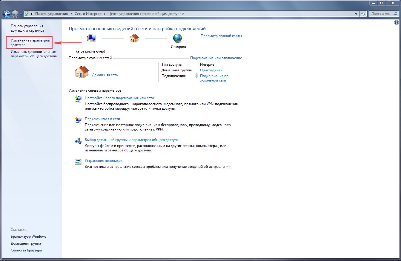
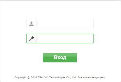
HC10 at G1>Gv1 and HC11 at 0 HC12 at G2>Gv2 and HC13 at 0 HC14 at G1>Gv3 and HC15 at 0 – with KG = 1 – the same as with KG=0 and assignment: G1=Gk1 at G1>Gin1 or G1=Gn1 at 0 G2=Gk2 at G2>Gv2 or G2=Gn2 at 0 G3=Gk3 at G1>Gv3 or G3=Gn3 at 0 Additionally, HC02 can be controlled, in the presence of which there is a transition to calculations using flow constants: – for KG=2 the same as for KG=0, as well as integration of volumes V1, V2, V3 using Gk1, Gk2 and Gk3, respectively, in the presence of HC02; – for KG=3 the same as for KG=1, as well as integration of volumes V1, V2, V3 using Gk1, Gk2 and Gk3, respectively, in the presence of HC02. C1, C2, C3 Volume sensor impulse price (0.000000…9.999999 m3). The price of the pulse BC is set according to the passport for the volume sensor. If the actual price of the pulse is indicated in the passport, which differs from the nominal price, then the actual price is chosen, thereby minimizing the measurement error. Gin1, Gin2, Gin3 Upper limit of the flow measurement range of the corresponding volume sensor (0… 99999.99 m3/h). If the current flow rate exceeds the value of the upper limit, then an abnormal situation is recorded, and when KG=1, not the actual flow rate, but the flow constant is involved in the calculations. Set according to the passport for the volume sensor. Gn1, Gn2, Gn3 Lower limit of the flow measurement range of the corresponding volume sensor (0…99999.99 m3/h). Replaces the measured flow rate at 0 Gk1, Gk2, Gk3 Flow rate constant for pipeline 1, 2 and 3 (0…9999.99 m3/h). If KG=1 or KG=3 is assigned, it replaces the measured flow rate through the corresponding volume sensor when G>Gv, and if KG=2 or KG=3 is assigned, the constants Gk1, Gk2 and Gk3 replace the measured flow value through the corresponding sensors, if available HC02. tk1, tk2, tk3 Temperature constant for pipeline 1, 2 and 3 (0…175 ºС). Replaces the measured temperature value of the corresponding sensor when this value goes beyond 0-176 ºС or in the absence of a sensor. Usually chosen in accordance with the contract for the supply of heat and coolant, for example, the maximum possible value for the respective pipeline. Pk1, Pk2, Pk3 Overpressure constant in pipelines 1, 2 and 3. (0…16 kg/cm2, bar; 0…1.6 MPa). Usually chosen in accordance with the terms of the contract for the supply of heat and coolant, for example, the maximum possible value for the relevant pipeline. Cold water temperature constant (0…100 ºС). It is used in calculations when the cold water thermometer is turned off or if it malfunctions. Usually appointed in accordance with the contract for the supply of heat and coolant. When calculating by the constants txk=0 and Pxk=0, the enthalpy of cold water is assumed to be zero. Cold water pressure constant (0…16 kg/cm2). Usually appointed in accordance with the contract for the supply of heat and coolant. When calculating by the constants txk=0 and Pxk=0, the enthalpy of cold water is assumed to be zero. The algorithm for using Mk. Determines the conditions for using the constant Mk instead of the difference of hourly masses (M1h–M2h), for schemes 0, 1 and 10 when calculating the hourly value of thermal energy and mass. The parameter can take the following values: 0 - Mk is not used; 1 – (M1h–M2h)=Mk at (–NM)M1h≤(M1h–M2h)<0; 2 – (M1h–M2h)=Mk at (M1h–M2h)< 0; 3 – (M1h–M2h)=Mk at (–NM)M1h≤(M1h–M2h)<0 и (M1h–M2h)= ρ3V3h at (M1h–M2h)< (–НМ)М1ч; 4 – (M1h–M2h)= ρ3V3h at (M1h–M2h)< 0 Unless otherwise specified in the contract with the power supply organization, the parameter AM is set to zero. Hourly mass constant (0…99999.99 t/h). When calculating thermal energy (on an interval of one hour) for schemes 0, 1 and 10, it replaces the calculated value (M1h–M2h), in accordance with the algorithm specified by the AM parameter. Unless otherwise specified in the contract with the energy supplying organization, the Mk parameter is set equal to zero. Mass unbalance setting (0.0000…0.0400). Determines the limit value of the maximum mass unbalance, when it is exceeded, i.e. at (M1h–M2h)<(–НМ)М1ч, происходит активизация НС16 (подробнее см. в гл. 7). It is determined taking into account the accuracy class of the flowmeters used as part of the heat meter. For example, for flowmeters with a relative error of 2%, it is possible to set the NM value equal to (2+2)/100=0.04. The parameter is set only for schemes 0, 1 and 10 at AM≠0. Calculation algorithm using Qk (0; 1; 2; 3; 10; 11; 12; 13). Parameter 1 determines the conditions for using the constant Qk instead of the calculated value of thermal energy on the hourly interval Qh. 0 - Qk is not used; the actual measured and calculated value is always added to the archive and to the total heat meter; 1 - Qk is used with a negative value of Qh, while HC17 is activated; 2 – the same as when AQ=1 and/or when the difference between the hourly masses M1h–M2h (for schemes 0, 1 and 10) goes beyond the allowable range determined by the HM parameter (when HC16 is activated); 3 – the same as in case of AQ=2 and/or in case of exceeding the permissible limits of parameter values from any of the primary temperature transducers (i.e. when an emergency situation HC08 or HC09 is activated). It does not matter how long the parameter was out of range; 10 - Qk is used for the time while HC04 is active; 11 - Qk is used for the time while HC04 is active and with a negative value of Qh; 12 – the same as with AQ=11, and/or when the difference between the hourly masses M1h–M2h (for schemes 0, 1 and 10) goes beyond the allowable range determined by the HM parameter (when HC16 is activated); 13 - the same as with AQ=12, and/or when the parameter values from any of the primary temperature transducers go beyond the permissible limits (i.e., when an emergency situation HC08 or HC09 is activated). Hourly heat constant (0…9999.99) [Gcal, GJ, MWh]. Change of hours to winter and summer time. When assigning PL=0, the clock change is not carried out. If PL=1, the clock will automatically be moved back one hour at 3 am on the last Sunday in October and forward one hour at 2 am on the last Sunday in March. Control of the signal at the discrete input. (0; 1; 2). 0 – control disabled; 1 – activation of HC02 in the presence of a signal; 2 – activation of HC02 in the absence of a signal. Network number (0…99). Used in requests from a computer or APS45 printer adapter. If several heat meters are connected in parallel, their network numbers must be different, otherwise the devices cannot be uniquely identified. When operating a single device with any of the listed types of equipment, the network number can be omitted. Identifier (0…99999999) Used to organize information received from a large number of metering devices in centralized data collection and processing systems. The identifier is usually set to the serial number of the device. Interface configuration (0;1;2;10;11;12). 0 - connection of the APS45 adapter, computer or other equipment at a speed of 2400 bps; 1 - connection of a telephone modem or a GSM modem operating on CSD technology (9600 bps); 2 - connection of a telephone modem or a GSM modem operating on CSD technology (19200 bps); 10 – connection of a GSM modem for operation using GPRS technology with a fixed IP address (2400 bit/s); 11 - connection of a GSM modem for operation using GPRS technology with a fixed IP address (9600 bps); 12 - connection of a GSM modem for operation using GPRS technology with a fixed IP address (19200 bps). The value of this parameter does not affect communication with external equipment via the optical port. In the absence of external equipment, it is recommended to set the value of CI=0. This appointment will increase battery life. The beginning of the allowed time interval for the modem. It is set in the hour-minute format (00-00…23-59). End of allowed modem time interval. It is set in the hour-minute format (00-00…23-59). Another option for using the VMH and VMK parameters is to control the number of rings before auto-answer. To do this, set VMN=VMK; the number of calls to auto answer will be equal to the number of minutes in the parameter value. When the number of minutes is less than three, an auto answer is assigned to the second call. The value of the first two digits of this parameter can be arbitrary. Changes related to setting the number of rings before auto-answer come into effect no later than 30 minutes from the moment you enter the value of the VMN and VMK parameters. If you want these changes to take effect immediately, you should run a Standard Modem Function Test (SETUP-TST-MODEM-STD). Print daily reports (1; 0). Enable/disable automatic printing of daily heat input reports. If PS=1, daily, at the checkout time, the archived data for the past day are placed in the print queue. Jobs in the queue will be printed upon request from the printer adapter APS45. The settings of this parameter do not determine the conditions for outputting reports to a computer and a reader. Print monthly reports (1; 0). Enable/disable automatic printing of monthly heat input reports. The settings of this parameter set the mode of automatic output of monthly reports to the printer in the same way as the settings of the FS parameter. Password for remote access. It is set by the user as a sequence of numbers and letters of the Latin alphabet. The maximum number of characters in a password is 8. For effective data protection, you should choose passwords of the maximum length. To disable data protection with a password, set PW=0. Password protection does not take effect when accessed via the optical port. Password protection is disabled when CI=0 is assigned. Control of the value of one of the current parameters for the condition of going beyond the limits of the range specified by the settings UN…UV. The parameter can take the following values: 0 – control is disabled; 1 – control is enabled; When the control is on and the parameter goes beyond the limits of the range UN…UV, HC04 is activated. The number of the parameter whose value is monitored for compliance with the settings. It can take a value from 0 to 5, corresponding to the following parameters: The current parameter, the value of which is controlled by the settings, is marked in the TEK section with the "bell;" symbol. Upper setting. (-999999.9…999999.9). The upper limit of the range against which one of the current parameters is controlled. Lower setting. (-999999.9…999999.9). The lower limit of the range against which one of the current parameters is monitored. Setup data lists are always available for viewing. Any parameter can be displayed on the display by scrolling through the list using the ↓ and . The entry and modification of setup data is carried out in the so-called non-secure mode, when the data protection switch is in the down position. When it is set to the top position, any data changes are blocked, and a stylized image of a lock appears on the display. However, if, according to the operating conditions, it is necessary to change the values of any parameters without unsealing the device, then this can be provided for when describing them in the database. Such parameters are marked with the symbol "" and are called operational. Data entry begins and ends by pressing the ENTER key, and is carried out using the ← and → keys (selection of familiarity), ↓ and (selection of numbers from 0 to 9 and the symbols "," and "–"). To set (remove) the sign of an operational parameter, you must press the ENTER key, after pressing and holding the ← key. Figure 5.6 illustrates the sequence of actions for data entry. The parameter values are given as an example. Figure 5.6 – Entering the numerical value of the parameter CP=25 5.3.2 TCT-LOOP mode (SET-TCT-LOOP) X4, X5, X6 Input signal value [Hz] on the corresponding connector. Measured in the range from 0.0008 to 1000 Hz with relative error not more than 0.01%. X7, X8 Input signal value [Ohm] on the corresponding connector. Measured in the range of 100-160 ohms with absolute no more than 0.04 Ohm. 5.3.3 TST-MODEM mode (SET-TST-MODEM) This item contains a number of service functions for working with telephone and GSM modems Standard modem function test (SETUP-TST-MODEM-STD) The test allows you to judge the correct connection and configuration (initialization) of the modem. The test works with both telephone and GSM modems. If the modem is configured and connected to the device correctly (according to the recommendations published on the website www.logika.spb.ru), the result of the test should be the Rx:OK message displayed on the device display (Fig.5.7). The number "2" in the first line corresponds to the number of rings before auto answer and is given as an example. Figure 5.7 - The image on the scoreboard with a successful test If errors occur or if the modem does not respond, the message Rx: Error or Rx: No response will be displayed on the display. Information about the GSM modem (SETUP - TST-MODEM-GSM) Scrolling through the information on the display is carried out using the and ↓ keys. An example of output information is shown in Figure 5.8. Figure 5.8 - Information displayed on the display in the mode SET-TST-MODEM-GSM. The output of the IP address of the GSM modem is carried out if the data is transmitted using GPRS technology, which should be reflected in the modem settings and the heat meter's configuration database (CI parameter). Account status request (SETUP-TST-MODEM-MF) In this mode, a request for a report on the current state of the subscriber's cash balance is sent to the mobile operator. Transferring a request takes some time, during which the message Transmitting a request is displayed on the instrument panel. After receiving, the operator's response is displayed on the scoreboard. Otherwise, the message No response is displayed. Before proceeding with setting up the router, let's check the LAN connection settings. For this: Windows 7 Click on " Start", "Control Panel". Then click on " View network status and tasks". LAN connectionProperty". Then select from the list Internet Protocol Version 4 (TCP/IPv4)"and press" Property". " and "", then press the button " Ok". Windows 10 Click on " Start", "Options". Then click on " Network and Internet". In the window that opens we see " ethernet". Click on it with the right mouse button, select " Property". Then select from the list IP version 4 (TCP/IPv4)"and press" Property". In the window that opens, you need to check the boxes " Obtain an IP address automatically" and " Obtain DNS Server Address Automatically", then press the button" Ok". The next step is to connect the router TP Link TL-WR941ND to your laptop or personal computer (PC). To do this, you need to connect the cable that the provider provided to you to the blue port of the router (that is, this is the cable that goes to your apartment, house, office, etc. from outside), and the cable that came with router, one end into one of the four ports that are marked in yellow on the router, and connect the other end to your laptop or PC. And yes, do not forget to connect the power cable. So, we connected the router, now you need to get into its web interface through any browser (be it Google Chrome, Mozilla Firefox, Internet Explorer, etc.). To do this, open the browser and in the address bar we drive in the address of the router: 192.168.0.1
and press the button " Enter" on your keyboard (in older models of this router, this address may be: 192.168.1.1
). So, we drive in the data and click " Entrance" And finally, we got to the web interface of the router and now you need to configure the equipment. First of all, we will secure the wireless network by setting a password for wi-fi. Then you will need to find out what type of connection is used to access the Internet, is it PPTP, L2TP or PPPOE. You can find out by calling your provider (this is the organization with which you have entered into an agreement to provide Internet services). So, let's start setting up the router. I bring to your attention Video instructions for setting a password for wi-fi on a router Tp-Link TL-WR941ND Let's also take a written and illustrative look at setting a password for wi-fi on a router Tp-Link TL-WR941ND. Next, go to the menu in the tab " Wireless security". Here we will configure the password for the wireless network invented above, for this we select the type of encryption" WPA/WPA2-Personal(Recommended)" and then below in the " PSK password"we come up with and drive in a password. Then click" Save". After we pressed " Save"an inscription will appear above this button indicating that the settings have been saved and now we need to restart the router. What we do by clicking on the button" click here" by sending the router to reboot. After rebooting, the name of your wireless network will appear in the network settings of your computer. PPTP on the router Tp-Link TL-WR941ND using the example of a Tp-Link TL-WR1043ND router. Let's also write and illustratively PPTP on the router Tp-Link TL-WR941ND. Consider connection setup PPTP with static IP on the router Tp-Link TL-WR941ND. Consider connection setup L2TP on the router Tp-Link TL-WR941ND. Consider connection setup L2TP with static IP on the router Tp-Link TL-WR941ND. I bring to your attention Video instructions for setting up the type of connection PPPOE on the router Tp-Link TL-WR941ND using the example of a Tp-Link TL-WR1043ND router. PPPOE on the router Tp-Link TL-WR941ND. Consider connection setup PPPOE with static IP address on the router Tp-Link TL-WR941ND. I bring to your attention Video instructions for changing the password on the web interface of the router Tp-Link TL-WR941ND using the example of a Tp-Link TL-WR1043ND router. If you have set a password on the web interface of the router and forgot it, I suggest you watch the Video instruction on resetting the password of the web interface on the router Tp-Link TL-WR941ND using the example of a Tp-Link TL-WR1043ND router. I bring to your attention Video instructions for updating the firmware on the router Tp-Link TL-WR941ND using the example of a Tp-Link TL-WR1043ND router. After connecting and configuring the router, you need to connect the computer to a wireless network (wi-fi), consider connecting to wi-fi in two operating systems, these are Windows 7 and Windows 10: Windows 7 Video instruction Sultan Connect automatically" and press Windows 10 Video instruction In the lower right corner of the desktop we find the icon for the wireless network (wi-fi), click on it with the left mouse button. A window pops up with a list of available wireless networks. We select a wireless network, in my case it is a network " Sultanova"(You choose the network whose name was given when). After selecting a network, check the box next to " Connect automatically" and press " connect". We wait, perhaps a couple of seconds, and you are connected to your wireless network. We continue to deal with the work of different routers in repeater and bridge modes. In this manual, we will take a closer look at setting up a Tp-Link router in bridge mode (WDS). I think that you immediately need to understand the question of what is WDS on Tp-Link routers and how it differs from the "Repeater" (repeater) mode of operation. I will say right away that on Tp-Link routers, there is no such mode as a repeater, such as Asus and Zyxel (there, routers really work like ). Only access points from Tp-Link can work as network repeaters. As for conventional routers, such as: TL-WR941ND, TL-WR740N, TL-WR841N, TL-MR3220, TL-WR842ND and other models, they have the ability to configure the bridge mode, aka WDS. Update: in the settings of some TP-Link routers, it became possible to configure the router to work as a repeater. Look, perhaps in the settings of your router there is such an opportunity. What is the difference between bridge mode and repeater mode? I explain in simple language: in bridge mode, we simply connect two routers via Wi-Fi. This mode can also be used to expand the Wi-Fi network. For example, we have some kind of main router that distributes the Internet via Wi-Fi. And we need to expand this network, increase its range. We take a Tp-Link router, set up the bridge mode on it according to this instruction, it receives the Internet via Wi-Fi from the main router, and distributes it further. But, unlike a repeater, you will have another wireless network, with its own name and password. Of course, the repeater (or router in repeater mode) much better for this job. It simply clones and amplifies an existing network, and in bridge mode, another wireless network appears. And you will have to choose which network to connect to. In the comments, I was recently asked this question: Good afternoon. The question arose, how to configure the tl-wr941nd router to receive Wifi, and then transfer the Internet via cable. That is, just use it as a receiver. Is it possible to do this somehow? By setting up your Tp-Link in WDS mode, it can be used as a receiver. To connect to the Internet, for example, a TV or a computer that does not have a Wi-Fi receiver. A few more points: 1 First of all, we need to change the wireless network channel on the main router. Please note that the router to which we will connect in bridge mode must be configured. That is, the Internet must work, it must distribute a Wi-Fi network. My main router is D-link DIR-615 .. So, we need to set a static channel for the wireless network in the settings on the main router. I don’t know what kind of router you have, therefore, see the instructions. In it, I wrote about changing the channel on devices from different manufacturers. If, for example, you also have Tp-Link as the main router, then the channel can be changed in the settings (which open at 192.168.1.1 (192.168.0.1), or see the instructions), on the tab Wireless. In field Channel specify a static channel. For example 1, or 6. Press the button Save to save the settings. A static channel has been established. You can exit the settings of the main router. First, we need to change the IP address of our Tp-Link. This is necessary so that there are no two devices with the same IP on the network. For example, if the main IP address is 192.168.1.1, and the second IP address is 192.168.1.1, then an address conflict will result. Go to the tab network - LAN. In field IP address change the last digit from 1 to 2. You will get the address 192.168.1.1, or 192.168.0.1. Click the button Save. The router will reboot. We need to know what is the IP address of the main router to which we are going to connect. If it has 192.168.1.1, then on the router that we want to connect via WDS, change the address to 192.168.1.2. And if the main address is 192.168.0.1, then the second one is set to 192.168.0.2. It is important that they are on the same subnet. Go to the settings again, only the IP address will be different - 192.168.1.2. which we have indicated above. 3 Click the Wireless. In field Wireless Network Name you can specify the name of the second wireless network. And in the field Channel be sure to specify the same channel that was set in the settings of the main router. I have channel 1. Select from the list the desired network from which the router will receive Internet. Opposite the desired network, click on the link Connect. 4 We are left only opposite the drop-down menu key type choose the type of security for your network (to which we are connected). And in the field Password enter a password for this network. To save, click on the button Save. Reboot your router. By turning off the power and turning it back on, or in the control panel by clicking on the link "click here". 5 After the reboot, go back to the settings. And right on the main screen (Status tab), look at the section Wireless. Against WDS Status should be written Run. This means that our Tp-Link will already connect to the main router. And it should distribute the Internet via Wi-Fi and cable. Setup completed. If you need the main router to issue IP addresses (not the one configured in bridge mode), then on the router that we just configured, you need to disable the DHCP server. You can do this in the settings, on the tab DHCP. By setting the switch near Disable and saving the settings. 6 Do not forget to put a password on the Wi-Fi network that the router we configured will distribute. You can see detailed. Everything is simple there. In settings, tab Wireless - Wireless Security, highlight an item WPA/WPA2 - Personal(Recommended), in field Wireless Password set a password (minimum 8 characters), and click the button below Save. Now our Tp-Link router receives the Internet from the main router, and distributes it further. Choose the right place to install the second router so that it is within the range of the main router. I decided to update this article and add up-to-date information on configuring WDS on TP-Link routers with new firmware. The one in blue. Everything is set up a little differently there. I'll show you now. If you have a router with a new control panel, then you need to go to the "Advanced Settings" - "System Tools" - "System Settings" section. If you have a dual-band router, then there you will see the opportunity to configure the bridge mode in two bands. At a frequency of 2.4 GHz and 5 GHz. 1 Check the "Enable WDS bridge" box next to the required frequency. For example, I checked the box next to 2.4 GHz. Click on the "Search" button 2 Select the network you want to connect to from the list. Just click "Select" next to your network. I think you can easily find your network in the list of available ones. 3 If necessary, you can change the protection settings (Protection, Password) and click on the "Save" button. If you set a password, then select "WPA-PSK / WPA2-PSK". You can also leave the network without a password. If needed. Roture via Wi-Fi will connect to another router, and will receive Internet wirelessly. If you need to disable the DHCP server, you can do this on the tab "Advanced settings" - "Network" - "DHCP server". If you make the settings that I showed above, then the Internet will only work via Wi-Fi, and when connected to a router (which is in WDS mode) cable, internet not working. Without internet access. This, of course, is not the case, and using a router as a Wi-Fi network receiver, for example, will not work. Therefore, I wrote a question to TP-LINK support, and they answered me. When setting up the WDS function, you receive IP addressing from the original router (the device to which the WDS client connects) both over a wired and non-wired network. To properly configure this function, you must disable the DHCP server on the equipment on which the WDS bridge is configured. You also need its local IP address to be on the same subnet as the original router. I checked everything on the TP-LINK TL-WR740N, and indeed, after disabling the DHCP server, the Internet immediately started working over the network cable. Disabling DHCP is not difficult at all. In the router settings, open the tab DHCP, set the switch near Disable(disable) and save the settings. We reboot the router and everything works fine. I immediately got internet via cable. You can go to the settings of this router at the address that we set in the second step. Mine is 192.168.1.2. Update. Another solution to the problem when a WDS connection is established, but there is no Internet access. In the DHCP server settings on the router? which we configure in WDS mode, you need to register the LAN IP address of the main router as the "Default Gateway". If it doesn't help, try setting the IP address of the main router as a DNS server. Save your settings and reboot your router. Update. Often there is a situation when the router does not want to connect in bridge mode. There can be many reasons, of course. In the comments, Edward suggested one interesting solution - disable the WPS function on both routers. If you have problems setting up WDS mode, then you can try. Moreover, few people use the WPS connection, and this feature is often recommended to be disabled for security purposes and solving other problems with the wireless network. On TP-Link routers, this is not difficult to do. In the WPS (or QSS) section, you just need to disable this feature. And in the new firmware. You need to disable it on both routers. On the main one, and on which we are trying to set up a connection in bridge mode. More information (including devices from other manufacturers) can be found in this article:. There will be a question, advice, comments - write in the comments.


Connecting a TP-Link TL-WR941ND router to a computer

TP-Link TL-WR941ND router authorization

Configuring the Tp-Link TL-WR941ND router
Setting a password for wi-fi
On the Web interface, select the tab " Wireless mode"and get into" Wireless settings". Here it is necessary in the column " Wireless network name:" come up with and specify the name of your wireless network, this name will continue to glow when you connect to the network. Then select " Region:" - Russia. After that press " Save".

PPTP setup
Net", then " WAN".
AT " WAN connection type:"choose" PPTP/PPTP RussiaUsername:") and password (on the line " Password:IP Address/Server Name:
Connect automatically NOT Connect on demand
Save".
Setting up PPTP with a static IP address
So go to the menu in the tab " Net", then " WAN".
AT " WAN connection type:"choose" PPTP/PPTP Russia", below you will be prompted to specify the username (in the line " Username:") and password (on the line " Password:").
Static IP addressIP Address/Server Name:"), ip-address (in the line " IP address:"), subnet mask (in line " Subnet mask:"), default gateway (on line " Main gate:") and DNS (in line " DNS:"). All of the above data is provided to you by the provider (the organization that provided you with the Internet).
All this data is usually prescribed in the contract with the provider. If for some reason you can't find them, you need to call your provider's hotline and find out how to get them.
After you have entered all the necessary data, check the box next to " Connect automatically" (This setting will keep your Internet connection permanent, so if you NOT Unlimited tariff I recommend ticking the box next to " Connect on demand", that is, the Internet is connected only when you start using it).
After all the manipulations with the settings, press the button " Save".
Setting L2TP
So go to the menu in the tab " Net", then " WAN".
AT " WAN connection type:"choose" L2T/L2T Russia", below you will be prompted to specify the username (in the line " Username:") and password (on the line " Password:"). You will also need to specify the ip-address of the server (in the line " IP Address/Server Name:"). All of the above data is provided to you by the provider (the organization that provided you with the Internet).
All this data is usually prescribed in the contract with the provider. If for some reason you can't find them, you need to call your provider's hotline and find out how to get them.
After you have entered all the necessary data, check the box next to " Connect automatically" (This setting will keep your Internet connection permanent, so if you NOT Unlimited tariff I recommend ticking the box next to " Connect on demand", that is, the Internet is connected only when you start using it).
After all the manipulations with the settings, press the button " Save".
Setting up L2TP with a static IP address
Typically, a static IP address is provided to legal entities, or as an additional service to the basic tariff for individuals.
So go to the menu in the tab " Net", then " WAN".
AT " WAN connection type:"choose" L2T/L2T Russia", below you will be prompted to specify the username (in the line " Username:") and password (on the line " Password:").
Since the connection uses a static IP address, you check the box next to " Static IP address", then specify the ip-address of the server (in the line " IP Address/Server Name:"), ip-address (in the line " IP address:"), subnet mask (in line " Subnet mask:"), default gateway (on line " Main gate:") and DNS (in line " DNS:"). All of the above data is provided to you by the provider (the organization that provided you with the Internet).
All this data is usually prescribed in the contract with the provider. If for some reason you can't find them, you need to call your provider's hotline and find out how to get them.
After you have entered all the necessary data, check the box next to " Connect automatically" (This setting will keep your Internet connection permanent, so if you NOT Unlimited tariff I recommend ticking the box next to " Connect on demand", that is, the Internet is connected only when you start using it).
After all the manipulations with the settings, press the button " Save".
PPPOE setup
So go to the menu in the tab " Net", then " WAN".
AT " WAN connection type:"choose" PPPoE/PPPoE Russia", below you will be prompted to specify the username (in the line " Username:"), password (on the line " Password:Confirm the password:"). All of the above data is provided to you by the provider (the organization that provided you with the Internet).
All this data is usually prescribed in the contract with the provider. If for some reason you can't find them, you need to call your provider's hotline and find out how to get them.
After you have entered all the necessary data, check the box next to " Dynamic IP" and " Connect automatically" (This setting will keep your Internet connection permanent, so if you NOT Unlimited tariff I recommend ticking the box next to " Connect on demandConnect on schedule
After all the manipulations with the settings, press the button " Save".
Setting up PPPOE with a static IP address
Typically, a static IP address is provided to legal entities, or as an additional service to the basic tariff for individuals.
So go to the menu in the tab " Net", then " WAN".
AT " WAN connection type:"choose" PPPoE/PPPoE Russia", below you will be prompted to specify the username (in the line " Username:"), password (on the line " Password:") and password confirmation (on the line " Confirm the password:"). Since the connection uses a static ip address, you check the box next to " Static IP address", then specify the ip-address (in the line " IP address:"), subnet mask (in line " Subnet mask:").
All of the above data is provided to you by the provider (the organization that provided you with the Internet).
All this data is usually prescribed in the contract with the provider. If for some reason you can't find them, you need to call your provider's hotline and find out how to get them.
After you have entered all the necessary data, check the box next to " Connect automatically" (This setting will keep your Internet connection permanent, so if you NOT Unlimited tariff I recommend ticking the box next to " Connect on demand", that is, the Internet is connected only when you start using it, or " Connect on schedule", that is, the Internet works at a certain time specified by you).
After all the manipulations with the settings, press the button " Save".
Changing the web interface password
Resetting the web interface password
Firmware update
Connecting a computer to wi-fi


"Connection".


Setting up a bridge (WDS) on a Tp-Link router


Setting up a wireless bridge (2.4 GHz and 5 GHz) on the new firmware version


If the Internet does not work via cable in WDS mode


If you can't set up a WDS connection


