Do-it-yourself RF voltmeter with a linear scale. We measure the RF voltage with a digital multimeter
RF voltmeter with linear scale
Robert AKOPOV (UN7RX), Zhezkazgan, Karaganda region, Kazakhstan
One of the necessary devices in the arsenal of a shortwave radio amateur, of course, is a high-frequency voltmeter. Unlike a low-frequency multimeter or, for example, a compact LCD oscilloscope, such a device is rarely found on sale, and the cost of a new branded one is quite high. Therefore, when there was a need for such a device, it was built, moreover, with a dial milliammeter as an indicator, which, unlike a digital one, allows you to easily and visually evaluate changes in readings quantitatively, and not by comparing the results. This is especially important when setting up devices where the amplitude of the measured signal is constantly changing. At the same time, the measurement accuracy of the device when using a certain circuitry is quite acceptable.
There is a typo in the diagram in the magazine: R9 should be a resistance of 4.7 MΩ

RF voltmeters can be divided into three groups. The first ones are built on the basis of a broadband amplifier with the inclusion of a diode rectifier in the negative feedback circuit. The amplifier ensures the operation of the rectifier element in the linear section of the current-voltage characteristic. In devices of the second group, a simple detector with a high-resistance amplifier is used. direct current(UPT). The scale of such an RF voltmeter at the lower measurement limits is non-linear, which requires the use of special calibration tables or individual calibration of the device. An attempt to somewhat linearize the scale and shift the sensitivity threshold down by passing a small current through the diode does not solve the problem. Before the beginning of the linear section of the I–V characteristic, these voltmeters are, in fact, indicators. Nevertheless, such devices, both in the form of finished designs and attachments to digital multimeters, are very popular, as evidenced by numerous publications in magazines and on the Internet.
The third group of instruments uses scale linearization, when the linearizing element is included in the DCF circuit to provide the necessary gain change depending on the input signal amplitude. Such solutions are often used in professional equipment units, for example, in broadband high-linear instrumentation amplifiers with AGC, or AGC units of broadband RF generators. It is on this principle that the described device is built, the circuit of which, with minor changes, is borrowed from.
With all the obvious simplicity, the RF voltmeter has very good parameters and, of course, a linear scale that eliminates calibration problems.
The measured voltage range is from 10 mV to 20 V. The operating frequency band is 100 Hz…75 MHz. The input resistance is at least 1 MΩ with an input capacitance of no more than a few picofarads, which is determined by the design of the detector head. The measurement error is no worse than 5%.
The linearizing unit is made on the DA1 chip. Diode VD2 in the negative feedback circuit helps to increase the gain of this stage of the UPT at low input voltages. The decrease in the output voltage of the detector is compensated, as a result, the readings of the device acquire a linear dependence. Capacitors C4, C5 prevent self-excitation of the UPT and reduce possible pickups. Variable resistor R10 is used to set the arrow measuring instrument PA1 to the zero mark of the scale before taking measurements. In this case, the input of the detector head must be closed. The power supply of the device has no special features. It is made on two stabilizers and provides a bipolar voltage of 2 × 12 V for powering operational amplifiers (the network transformer is not conventionally shown in the diagram, but is included in the assembly kit).

All parts of the device, with the exception of parts of the measuring probe, are mounted on two printed circuit boards ah from one-sided foil fiberglass. Below is a photograph of the UPT board, the power board and the measuring probe.

Milliammeter RA1 - M42100, with a current of full deflection of the needle 1 mA. Switch SA1 - PGZ-8PZN. Variable resistor R10 - SP2-2, all tuning resistors - imported multi-turn, for example 3296W. Resistors of non-standard ratings R2, R5 and R11 can be made up of two connected in series. Operational amplifiers can be replaced by others with high input impedance and preferably with internal correction (so as not to complicate the circuit). All fixed capacitors are ceramic. Capacitor C3 is mounted directly on the input connector XW1.
The D311A diode in the RF rectifier was chosen from the point of view of the optimal maximum allowable RF voltage and rectification efficiency at the upper measured frequency boundary.
A few words about the design of the instrument's measuring probe. The body of the probe is made of fiberglass in the form of a tube, on top of which a copper foil screen is put on.

Inside the case there is a board made of foil fiberglass, on which the probe parts are mounted. A ring of tinned foil strip approximately in the middle of the body is provided to make contact with the common wire of a detachable divider, which can be screwed on in place of the probe tip.
The adjustment of the device begins with the balancing of the op-amp DA2. To do this, switch SA1 is set to the "5 V" position, the input of the measuring probe is closed, and the pointer of the device PA1 is set to the zero mark of the scale with a trimming resistor R13. Then the device is switched to the “10 mV” position, the same voltage is applied to its input, and the arrow of the RA1 device is set to the last division of the scale with the resistor R16. Next, a voltage of 5 mV is applied to the input of the voltmeter, the arrow of the device should be approximately in the middle of the scale. The linearity of the readings is achieved by selecting the resistor R3. Even better linearity can be achieved by selecting the resistor R12, however, it should be borne in mind that this will affect the gain of the UPT. Next, the device is calibrated on all subranges with the corresponding tuning resistors. As a reference voltage when calibrating the voltmeter, the author used an Agilent 8648A generator (with a 50 Ohm load equivalent connected to its output), which has a digital output signal level meter.
The entire article from the magazine Radio No. 2, 2011 can be downloaded from here
LITERATURE:
1. Prokofiev I., Millivoltmeter-Q-meter. - Radio, 1982, No. 7, p. 31.
2. Stepanov B., RF head for a digital multimeter. - Radio, 2006, No. 8, p. 58, 59.
3. Stepanov B., Schottky diode RF voltmeter. - Radio, 2008, No. 1, p. 61, 62.
4. Pugach A., High-frequency millivoltmeter with a linear scale. - Radio, 1992, No. 7, p. 39.
The cost of printed circuit boards (probe, main board and power supply board) with a mask and marking: 80 UAH
One of the most necessary devices in the arsenal of a shortwave radio amateur is certainly a high-frequency voltmeter.
Unlike low-frequency multimeters and inexpensive, compact LCD oscilloscopes, such devices are much rarer, and new, proprietary ones are also quite expensive.
Therefore, it was decided to collect homemade device, subject to the usual requirements.
When choosing a display option, I settled on analog. Unlike digital, analog indication allows you to easily and visually evaluate changes in readings quantitatively, and not just by comparing results. This is especially important when setting up circuits where the amplitude of the measured signal is constantly changing.
At the same time, the accuracy of measurements with the appropriate circuitry is quite sufficient.
As a rule, there are two types of RF voltmeters. Firstly, broadband amplifiers are used, which ensure the operation of the detector element in the linear section of the current-voltage characteristic, or by including a rectifier in the OOS circuit of such an amplifier.
Secondly, a simple detector is used, sometimes with a high TCA. The scale of such an RF voltmeter is non-linear at the lower measurement limits and requires the use of special tables or individual calibration of the scale.
An attempt to linearize the scale to some extent, as well as to shift the sensitivity threshold down, by passing a small current through the diode, does not solve the problem. The resulting RF voltmeters before the start of the linear sections of the CVC remain, in fact, indicators. Nevertheless, such RF voltmeters, both in the form of complete instruments and in the form of attachments to digital multimeters, are very popular, as evidenced by numerous publications in magazines and on the Internet.
There is another way to linearize the measuring scale, when a linearizing element is included in the DCF circuit, providing the necessary gain change depending on the amplitude of the input signal.
Such circuits are often used in professional equipment nodes, for example, in broadband high-linear instrumentation amplifiers with AGC. It was on the basis of such a solution that the device described here was created.
The author of this article for the first time assembled such a device around the years of its publication, recently reassembled, moved to another case, on new printed circuit boards and for new components.
With all the obvious simplicity of the circuit, this RF voltmeter provides very good parameters.
The range of measured voltages (final divisions of the scale) is from 10mV to 20V. Frequency range from 100Hz to 75MHz, input impedance not less than 1MΩ, with input capacitance not more than a few pF (determined mainly by the design of the RF head). And, of course, it has a linear scale, eliminating problems with graduation. Measurement accuracy, with high-quality settings, is not worse than 5%.
The scheme of the device is shown in Figure 1.
Rice. one
Structurally, the device consists of three parts. Measuring detector (HF head), UPT board with linearization unit and stabilizer board.
The linearizing unit is made on the OP1 chip with a diode in the OOS circuit. Due to the presence of negative feedback diode D2, the gain of this stage of the UPT increases at low input voltages. Due to this, the decrease in the output voltage of the detector is compensated and the scale of the device is linear.
Capacitors C4, C5 prevent self-excitation of the UPT and reduce possible pickups.
The device used in the voltmeter for a current of 1mA.
Resistors of non-standard ratings consist of 2. You can use any op amp with a high input impedance. Capacitor C3 is mounted directly on the input BNC connector.
Resistor R7 happens to promptly set the head arrow to 0. In this case, the RF head must be closed at the input.
Setting up the device begins with balancing the amplifier on the op-amp OP2. To do this, the measurement limit switch is set to 5V, the RF head is closed and the instrument pointer is set to 0 with a tuning resistor R13. Next, we switch to 10mV, apply the same voltage, set the arrow to the last division of the scale with resistor R14. We apply 5mV to the input, the arrow should be approximately in the middle of the scale. We achieve linearity by selecting the resistor R2.
Next, we calibrate the device on all subranges with the corresponding tuning resistors.
Appearance of the finished device: 
RF detector head 
Drawings of printed circuit boards of a voltmeter and stabilizers can be taken
Millivoltmeters with a linear scale, described in the literature, are traditionally performed according to the circuit with a diode rectifier included in the negative feedback circuit of the AC amplifier. Such devices are quite complex, require the use of scarce parts, in addition, rather stringent design requirements are imposed on them.
At the same time, there are very simple millivoltmeters with a non-linear scale, where the rectifier is assembled in an external probe, and a simple DC amplifier (UCA) is used in the main part. According to this principle, a device was built, the description of which was proposed in the journal Radio, 1984, No. 8, p. 57. These devices are broadband, have high input impedance and low input capacitance, and are structurally simple. But the readings of the device are conditional, and the true value of the voltage is found either from calibration tables or from graphs. When using the node proposed by the author, the scale of such a millivoltmeter becomes linear.
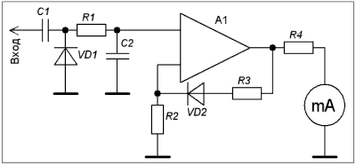
Fig.1
On fig. 1 shows a simplified diagram of the device. The measured high-frequency voltage is rectified by the diode VD1 in the remote probe and through the resistor R1 is fed to the input of the UPT A1. Due to the presence of a negative feedback diode VD2 in the circuit, the amplification of the UPT at low input voltages increases. Due to this, the decrease in the voltage rectified by the VD1 diode is compensated and the scale of the device is linearized.

Fig.2
Millivoltmeter, made by the author, allows you to measure voltage in the range of 2.5 mV ... 25 V on 11 subranges. Operating frequency band 100 Hz...75 MHz. The measurement error does not exceed 5%.
circuit diagram device is shown in Fig.2. The linearizing stage, made on the operational amplifier DA1, operates on the subranges "0 ... 12.5 mV", "0 ... 25 mV", "0 ... 50 mV" "0 ... 125 mV", " 0...250 mV", "0...500 mV", "0...1.25 V". On the remaining subranges, the amplitude characteristic of the VD1 diode is close to linear, so the input of the final stage (on the DA2 chip) is connected to the probe output through a resistive voltage divider (R7 - R11). Capacitors C4-C6 prevent self-excitation of the operational amplifier DA2 and reduce possible pickups at its input.
The device uses a milliammeter with a total deflection current of 1 mA. Adjusted resistors R14, R16-R23 - SP5-2. Resistor R7 is made up of two 300 kΩ resistors connected in series, R10 and R11 are two 20 kΩ resistors. Diodes VD1, VD2 - germanium high-frequency.
Operational amplifiers KR544UD1A can be replaced by any other with a high input impedance.
There are no special requirements for the design of the device. Capacitors Cl, C2, diode VDI and resistor RI are mounted in a remote head, which is connected to the device with a shielded wire. The axis of the variable resistor R12 is displayed on the front panel.
The adjustment begins with setting the arrow of the measuring device to zero. To do this, switch SA1 is switched to the “25 V” position, the input of the device is connected to the case, and the necessary adjustment is made by resistor R14. After that, they switch to the “250 mV” range, by adjusting the resistor R12 set the arrow of the measuring device to zero and by selecting the resistor R2 they achieve the best linearity of the scale. Then check the linearity of the scale on the remaining ranges. If linearity cannot be achieved, one of the diodes should be replaced with another instance. Then trimming resistors R16-R23 calibrate the device on all ranges.
Note. We draw the attention of readers that, according to the reference data, the maximum constant and impulse reverse voltages for the remote probe used by the author of the article (GD507A diode) are equal to 20 V. Therefore, not every instance of this type of diodes will be able to ensure the operation of the device on the last two subranges.
A. Pugach Tashkent
Radio, No. 7, 1992
To establish various RF devices (receivers, transmitters ...), it will not work to measure the signal level with a conventional voltmeter. Therefore, here it is necessary to use an RF voltmeter.
One of these proposed below is a simple RF millivoltmeter circuit with two transistors.
Schematic diagram of the RF millivoltmeter

The DC millivoltmeter circuit is built on transistors VI.1 and VI.2 and a high-frequency voltage rectifier on diode V2.
The use of an integrated transistor assembly makes it possible to minimize the imbalance of the millivoltmeter DC amplifier due to changes in ambient temperature.
As V2, it is advisable to use a silicon diode designed to mix signals or detect them in the decimeter wave range.
You can also apply here some of the pulse diodes designed for high-speed switches. The temperature compensation of the diode V2 operation mode is provided by the forward-biased silicon diode V3.
The operating point of the rectifier diode V2 is set with a trimming resistor R9 according to its maximum sensitivity. The millivoltmeter is balanced (in the absence of an RF input voltage) with a trimming resistor R 7.
Calibrate the device using the tuning resistor R8.
The scale of the millivoltmeter is non-linear and it is made individually for each instance of the device.
Instead of an integral pair of transistors, you can also use individual transistors, matched by the same gain.
All components of the device are made on a printed circuit board.

In an RF millivoltmeter, you can use transistor assemblies K125NT1 or K166NT1A (moreover, one of the transistors in the assembly will successfully play the role of a heat-stabilizing diode) or the like, and also (as mentioned above) you can pick up a pair of transistors from the KT312, KT315 series, etc. (according to static current transfer coefficients at a fixed value of collector current and base-emitter voltage at a fixed value of base current).
Source: Designs of Soviet and Czechoslovak radio amateurs: Sat. articles. 1987. (MRB No. 1113)
P O P U L I R N O E:
You can make a real birdhouse so that starlings live in it.
And you can make a small toy birdhouse from ordinary matches.
Welcome to the site "Master Vintik"!

First site post
is a site for those who like to make, do something or repair with their own hands.
Here you will find a large number of easy-to-build diagrams, drawings, photos and video tutorials for beginners! The site contains diagrams, programs and a description of the repair of household imported and domestic equipment for free download. There are also guides and helpful tips for a wide range of readers!
Main site bookmarks
Bookmark there are simple but useful circuits for beginner radio amateurs.
Bookmark there are programs that can be downloaded for free, without registration and without SMS.
On the tab are: books for beginner radio amateurs, written in a simple and accessible form, as well as reference books on electronic components, codes for entering the service menu of the most common models of imported TVs (service manual).
Bookmark You will learn how to repair a TV, radio station, appliance or any device yourself.
Bookmark there are a large number (more than 600) of TV sets, radio stations of imported and domestic
production.
Bookmark many interesting and entertaining workshops. Crafts from plastic bottles, CDs, beading, soap making and many other exciting crafts.
The site is constantly updated with material and is used for informational purposes only. All material is taken from open sources and the rights belong to their respective owners. Part of the repair schemes and methods was developed by the authors of the Master Screw website.
If you like the site add to bookmarks at the top of your browser.
you also can
Another prefix to the multimeter is an RF Schottky diode voltmeter.
The description of the device has already been given on the pages of our site, the theoretical basis of which was the publication of B. Stepanov in the journal "Radio" (see the list of references at the end of the note). At that time, analog pointer devices were used as measuring heads. In the 1990s and the first decade of the 21st century, in connection with the mass distribution of small-sized and inexpensive digital multimeters, their widespread use in amateur radio practice began.
In 2006, in the journal "Radio" No. 8, B. Stepanov brought the RF head circuit to a digital multimeter with good enough linearity for use at frequencies up to 30 MHz and sensitivity up to 0.1 V or less. It uses a germanium diode GD507.
In "Radio" No. 1 - 2008, p. 61-62, B.Stepanov in the article "HF voltmeter on the Schottky diode" cited a probe circuit with diodes BAT -41. The author realized the idea: when a small direct current is passed through the diode in the forward direction, a voltmeter with such a probe (head) already allows you to measure the RF voltage up to 50 mV.
A few words about the probe manufacturing technology. The body is made of tinned elastic sheet (the body of SKD-24 is cut and bent). In the middle it is separated by a partition made of one-sided foil fiberglass. On the side of the partition, where the foil remained, a surface-mounted circuit of the RF probe was made (Fig. 1, 3).
Fig.1
Two Schottky diodes are placed close to each other in a common PVC tube to minimize the temperature dependence (voltage drop). On the other side of the partition is the power compartment. It comes with two AA batteries.

Fig.2
The probe is connected to the multimeter with a two-wire shielded wire (Fig. 2). After balancing the probe with the help of resistor R 2, the RF voltage is measured. Its reading is carried out on a voltmeter scale of 200 (2000) mV.
Fig.3

Fig.4

Fig.5
In advance we inform radio amateurs- you can find the full author's description of the work of this design, its theoretical justification and practical implementation in the number indicated in the note Radio magazine.
Literature:
1. B. Stepanov. Measurement of small RF voltages. Zh. "Radio", No. 7, 12 - 1980, p.55, p.28.
2. B. Stepanov. High frequency millivoltmeter. Zh. "Radio", No. 8 - 1984, p.57.
3. B. Stepanov. RF head to digital voltmeter. Zh. "Radio", No. 8, 2006, p.58.
4. B. Stepanov. RF voltmeter on a Schottky diode. "Radio", No. 1 - 2008, p. 61-62.


