Clone pi avr metal detector reviews. Overview of the finished metal detector board Clone PI AVR
Metal detector Clone this is a slightly revised and simplified version of the Tracker PI (Koschei 2I) metal detector. Since the Tracker PI metal detector is a commercial device, and its firmware is closed from free access. And our radio amateurs are persistent people, jointly and mainly by Andrey Fedorov, the circuit and firmware of the Clone PI metal detector were developed and made freely available and every radio amateur, with basic knowledge in electronics, can assemble it.
The Clone metal detector has many variations of boards, circuits and firmware versions, which have been repeatedly modified and reworked by many radio amateurs. Hard-to-reach components were replaced with more accessible ones, for example, the ADC that was used in the first version of the metal detector was removed from the circuit in the process, due to its rarity, etc.
The most popular two versions of the metal detector today: Clone PI-AVR and Clone PI-W.
Metal detector Clone PI-AVR DIY
IN OUR ONLINE STORE YOU CAN BUY A READY METAL DETECTOR BOARD CLONE PI AVR
Distinctive features of the Clone PI-AVR version of the metal detector:
- The available ATmega8 controller from Atmel was used.
- Instead of an external ADC, the internal ADC of the controller is used.
- Used clocking from the internal RC generator of the controller.
Photo of the printed circuit board (This is the most decent version of the Clone PI AVR metal detector)

Photo of the assembled boards of the Clone PI AVR metal detector


Setting Configuration Bits for Microcontroller Firmware

An example of a finished Clone PI-AVR metal detector photo

Metal detector Clone PI-W DIY
Distinctive features of the Clone PI-W metal detector:
- Maximum simplification of the circuit and reduction in the number of parts
- LED indication of 10 LEDs. LEDs make it possible to make an underwater metal detector Clone. The LEDs are visible underwater and are easier to seal.
Diagram of the Clone PI AVR metal detector


Setting the Configuration Bits to Flash the Microcontroller

Download Archive with printed circuit board, firmware and schematics of the Clone PI-AVR metal detector(
An example of a finished Clone PI-W metal detector photo:


Coil for metal detector Clone PI
For the Klon metal detector, you can use Koschey 5I, as well as depth frames for Koschey 5I (True, the depth will be somewhat inferior to Koschey 5I, because there is no "turbo mode" in Klon, and the clone has a little less power). There are a lot of descriptions of various designs for pulse metal detectors on the Internet, so the choice is great.
The most versatile coils are coils with diameters of 250 - 280 mm. They see well both small objects (Coins, cartridge cases, etc.) and large metal at a depth of 1 - 1.5 meters.
Standard sensor for a metal detector Clone 25 - 27 turns, winding wire with a diameter of 0.5 - 0.8 mm is wound in bulk, on a mandrel with a diameter of 19 cm. The larger the diameter of the coil, the greater the search depth and the less sensitivity to small objects.
The easiest way to make a clone metal detector coil is a twisted pair coil. A description of the manufacture of such a coil can be found in the article " Coils for pulsed twisted pair metal detectors". Or you can buy ready-made coil for metal detector(All coils for the Tracker PI-2 and Koschey 5I metal detectors are suitable).
Advantages and disadvantages of the Clone metal detector
Advantages of the Clone metal detector compared to the Tracker PI-2 metal detector:
- Simpler circuit (fewer parts).
- There is no dependence of sensitivity on the degree of battery discharge.
- Button control, not variable resistors.
- Openness of the firmware, and availability for self-production.
Flaws:
- Less stable operation, and greater sensitivity to interference.
- Significantly higher power consumption (100 - 160 mA for the Clone W version, and up to 250 mA for the AVR version), and correspondingly shorter battery life or batteries.
- Poor repeatability of characteristics (This is the personal opinion of the author of this article, and it can be disputed. I had personal experience in assembling 5 Clone PI metal detectors and they all worked differently, 2 were good, 1 was tolerable, and 2 more worked disgustingly and constantly bugged).
Conclusion: Clone metal detector is a good solution for radio amateurs, and for those who want to assemble a metal detector with their own hands, this is a normal pulse metal detector controlled by a microcontroller.But this is not an industrial metal detector, I would not advise you to buy it.
Although there are a lot of radio amateurs involved in the sale of clones. But the purchase of such a metal detector is fraught with great risks, due to the spread of real search characteristics and build quality. And in terms of work stability, even a perfectly assembled Clone is not even tracker D. It is better to buy the original from which he was "Clone" - Tracker PI-2, which has been tested over the years of work in a wide variety of conditions and has won many of its fans.
Write your questions, comments and suggestions for finalizing the article.
Clone Pi AVR this is a simplified and improved version of the metal detector popular with radio amateurs. Since in the manufacture of the Clone PI metal detector, many had difficulties with the purchase of an ADC, in new version AVR Clone metal detector, Peak controller and external ADC were replaced by an affordable AVR microcontroller with an internal ADC Atmega8.
Scheme of the metal detector Clone PI AVR

As well as the Clone PI AVR circuit with the specified DC voltages
 On the Internet, there are several options for breeding a printed circuit board for a Clone Pi AVR metal detector. Below is a photo of a quite decent version of the PCB.

One of the options for implementing the board of the metal detector Clone ABP:

To flash the microcontroller, the configuration bits must be arranged as follows:

Metal detector Clone PI AVR has an average level of complexity manufacturing, due to the presence in the metal detector circuit, of a programmable microcontroller. But otherwise, its manufacture should not cause any special difficulties.
Coil for metal detector Clone PI AVR
With the Clone PI AVR metal detector, you can use coils from the Tracker and Koschei pulse metal detectors, as well as large depth frames.
The most versatile coil diameters are 20-30 cm. Such coils will have a detection depth of 1 - 1.5 meters and will remain sensitive to small metal objects (coins, jewelry, etc.).
For the manufacture of a universal search coil, you need to wind 23-24 turns of winding enamel wire with a diameter of 0.7-0.8mm on a mandrel 26-27 cm. As a mandrel, you can use a saucepan of a suitable diameter, or make a mandrel as in the photo below:

To make a mandrel, we take a sheet of plywood or chipboard. On it, with the help of a compass, we draw a circle with the diameter we need. Then we take screws or self-tapping screws, we put cambric on them. We screw the screws with cambrics around the perimeter of our circle, and we get a mandrel for winding the coil.
The coil is wound in bulk. Then the turns are tightly wound together, with adhesive tape, or electrical tape. We solder the wire 2 * 0.75 mm in insulation to the ends of the winding.

We connect our coil to the board of the Clone Pi AVR metal detector (It is better to use a connector for connection) and check its performance. Such a coil is suitable for testing and experimentation, but for real work, it must be protected from shock, moisture, etc.
To do this, the coil must be fixed in a suitable plastic case. In our designs, we use such a universal case.
 The coil is fixed inside the body with hot glue, and then the coil body is sealed with dichloroethane, or twisted with stainless steel screws.
To obtain an underwater coil, it is better to fill the body with epoxy. This will reduce its buoyancy and prevent water from entering the inside of the hull.

And the article about describes how to make deep frames for pulsed metal detectors.
Firmware for metal detector Clone PI AVR:
- Firmware version 1.7.3 for ATmega8 —
- Firmware version 1.7.3A for ATmega8, with a modified auto-ground algorithm -
- Firmware version 1.8.0 for the controller ATmega8- Changes:
- The volume of the button sounds has been adjusted to match the main volume.
- Ground adjust now works in 3 modes - adaptive, fixing and off(static).
- Guard interval can now be picked up when enabled ( auto), use the stored value ( last), or be selected by the user forcibly in the range 2 … 80 .
- Added option volume raise, which allows you to reduce the volume at the beginning of the scale (with weak responses). This improves the stability of the circuit at a low threshold.
- Removed double power mode, which showed its practical uselessness.
- When the backlight is on, the letter “L” (Light) is displayed on the indicator.
- Firmware version 1.8.1 for the controller ATmega8, bugs fixed in firmware and power consumption reduced —
Conclusion: Clone PI AVR metal detector This is a proven and popular metal detector among radio amateurs and search engines. It has a search depth comparable to factory metal detectors and a completely open circuit and firmware for its manufacture. To shortcomings metal detector should be attributed to excessive power consumption.
Overview of the finished metal detector board Clone PI AVR
Video of the launch of the Clone PI AVR metal detector assembled by oneself, and the possibility of setting it up:
Materials used in the writing of this article:
- Developer site - http://fandy.hut2.ru
- And this site - http://metdet.ucoz.ua/publ/metalloiskatel_klon/1-1-0-13
- And also a forum - http://md4u.ru/viewtopic.php?f=5&t=660 - here you can ask questions about self-assembly of the metal detector.
Clone Pi-V is a simplified and cheaper version pulse metal detector(MD) Clone PI-AVR (which has a two-line LCD screen). Here is a description on the website of Andrey Fedorov - the author of all clones: http://fandy.hut2.ru/ClonePI_W.htm
The design of the Klon (or, as it is also called, the Elephant) metal detector turned out to be so successful that the rumor about it spread far beyond the borders of our country and the device deservedly gained international fame. I came across YouTube videos posted by radio amateurs in Greece, England, Germany and other European countries.
The main advantage of this device is that, despite the excellent characteristics, its circuit is so simple that even a beginner can assemble it. Correctly assembled circuit starts working immediately, the setting consists in adjusting a single trimmer. You can even do without an oscilloscope!
The only difficulty for beginners is the need to flash the microcontroller. But do not worry: any computer with a COM port and a simple circuit of literally several elements will do to flash this 28-foot centipede (more on that later).
But on the other hand, after overcoming all the difficulties, you will have a device capable of detecting a weaving nail at a bayonet depth (with a 20-centimeter coil). Soviet 5 kopecks in our heavy soil - at a depth of 25 cm, my 3 gram hoop in the air - 22 cm (flat) and - 10 cm (edge). I’m generally silent about cereals - a heating battery is 170 cm in air.
But the Clone also has disadvantages - the lack of discrimination of metals, i.e. he sees absolutely everything. And this extra effort when excavating, because you will have to dig everything in a row (there may be a coin, or there may be a cork from a bottle). He also has a weak sensitivity to gold.
Disk balancers are well suited for searching for gold (nuggets and jewelry). But to make such a metal detector, you need experience and understanding of the principle of operation of the device, otherwise nothing may work out. Of the available and good balancers, I recommend looking towards the Terminators. They are not inferior to many foreign brands, and in some respects even surpass them. For experienced radio amateurs to search for gold, I would recommend the Quasar metal detector with an elongated DD-coil (the so-called "narrow eggs").
In a word, if you need a device to search for ferrous metal, then Clone is your choice. You won't find anything easier or more efficient. For comparison, the vaunted Sturm is about 1.5 times inferior in detection depth. The good old Asya 250 is also far behind when searching for ferrous metals.
So, you already want such a device and are ready to start assembling it? Then let's go!
Schematic diagrams (3 options)
There are three of the best and repeatedly proven schemes that differ only in key chips:
- diagram with ADG444 (aka KR590KN5);
- scheme with KR590KN2 (only differs from the first printed circuit board);
- circuit with CD4066 (4016).
These circuits are 100% working, so no claims for their inoperability are accepted. If something doesn’t work for you, then it’s your own fault.
Which scheme is better?
KH5 is difficult to find, besides, there are many marriages among them (even cases are described when sunlight falling on the microcircuit caused self-excitation). If you come across a KN-ka after the 91st year of release or in a brown case, do not take it in any case - they are almost all defective.
KH5 has a complete analogue - ADG444, but these microcircuits are not very common, and besides, they are quite expensive (300-400 rubles).
Devices assembled on KH2 work a little more stable. But now it is almost impossible to get it.
Personally, my choice is a circuit using a 4066 key chip (third option). This microcircuit costs a penny (10 ... 25 rubles), it is sold everywhere, and at the same time it works without glitches.
But let's go in order.
Scheme with ADG444 (KR590KN5)

Purpose of elements
Resistor R1 is designed to dampen reverse pulses (ROI) in the sensor, arising from the phenomenon of self-induction. If it does not exist (for example, if there is a break or too much resistance), the IOC will heat a powerful field device (more precisely, a diode built into it), electrolyte C1, and can even break through the diode protection VD1, VD2 at the input of the analog part.
R3 also helps to reduce the quality factor of the sensor with a large signal amplitude (then this resistor is connected in parallel with R1 through diodes). By the way, the flair of a metal detector to some extent depends on the resistances R1 and R3, but not so much that you bother with their selection.
In the event of a break in the resistor R2, the field worker can get interference from the air and spontaneously open. In this case, huge currents will flow through the sensor, which will lead to burnout of the resistor R12. By the way, the resistance R12 can be anything within 1 ... 27 Ohm (small resistance - for more "deep" options).
Capacitor C3 in conjunction with R14 is part of an integrator that allows you to suppress random noise at the sensor input due to industrial interference. I usually set C3 = 0.047...0.068uF. The resistance R14 can be from 1.8 to 2.7 MΩ, there will be no noticeable difference.
If the device is well debugged and there are no false positives, then by increasing the value of R15 and decreasing C5, you can raise the device's flair to the maximum.
If the power is supplied from the battery, then C1 can be left at 2200 uF. If from weak batteries, then its capacity is better to increase significantly. For example, up to 6800 uF. It is this electrolyte that serves as a source of energy for the formation of powerful short current pulses through the coil.
Used components and their estimated price(August 2017):
| Designation | Name | Comment | Price | Qty |
|---|---|---|---|---|
| Microcircuits | ||||
| U1 | ATmega8 | ATmega8A-16PU and ATmega8A-PU are interchangeable, firmware and configuration bits are exactly the same. | 110 rub | 1 |
| U2 | 78L05 | 10 rub | 1 | |
| U3 | TL074 | Sometimes it's worth playing with the TL074 opamp - try from a different batch (different year). It happens that one is normal, while the other has almost zero gain. If you choose this chip properly, you can win another couple of centimeters of chuyka. Can be replaced by 2pcs TL072. |
25 rub | 1 |
| U4 | KR590KN5 (ADG444) | As it turned out, the stability of the device and the search range are affected not only by the selection of the TL074 op-amp, but also by the KH5 switch microcircuits - the best result for microcircuits produced before 1993, and excellent - for microcircuits in planar metal-ceramic packages (1984 onwards). They can be installed directly on the board without changing the signet. The bourgeois version of AGD444 does not cause any complaints. By changing the printed circuit board accordingly, the KH5 (444) chip can be replaced with 590KN2 or CD4066CN (see below for more on this). |
206 rub | 1 |
| U5 | TL431 | Analog K1156ER5. | 15 rub | 1 |
| transistors | ||||
| VT1 | IRF740/TO | Analogues: KP776A, IRF630, IRF640, IRF840, BUZ73, 04N60, 5N60. Any n-channel field device will do, the drain-source is at least 200 volts, 2 amperes, the gate capacitance is not more than 1200 pF. | 35 rub | 1 |
| VT2 | BSN304A | Instead of BSN304A, you can use the more affordable BS170. It can also be replaced with a C945, 2N7000 or KP501A transistor. | 6 rub | 1 |
| Diodes | ||||
| VD1, VD2, VD14-VD17 | 1N4148 | Ours can be: KD521, KD522. | 1 rub | 6 |
| VD4-VD13 | Instead of domestic diodes, it is better to put super-bright ones (ours are not visible at all in the sun, and for bright ones, a protective visor from the sun would not hurt). | 15 rub | 10 | |
| Capacitors | ||||
| C1 | 2200uF 16V | We definitely set this capacitor to 4700 microfarads (or even better 6800, 10000) - and the stability of the device increases and when the voltage drops on the battery (if it is old or not charged), it will help. In addition, the charge per impulse of the device increases. | 63 rub | 1 |
| C3 | 0.1uF | It is better to set 0.047uF (if its capacitance is increased, the feel drops, and if it decreases, stability drops). So the golden mean. Ideally, this capacitor (like C5) should be a film capacitor. But you shouldn’t drive too hard, our KM or imported ones (almost any, except for mica, of course) - mylar, palladium, etc. will do. You can even put dark green Chinese pads from old broken equipment. | 10 rub | 1 |
| C4, C10, C11, C14 | 0.1uF | 5 rub | 4 | |
| C5 | 2200pF | It is possible at 1500pF, the main thing is that it be thermally stable (like C3). Personally, I set both 1500 pF and 2200 pF - I didn’t notice much difference. | 10 rub | 1 |
| C6 | 220uF 16V | 15 rub | 1 | |
| C7 | 470uF 6.3V | 12 rub | 1 | |
| C9, C12 | 0.01uF | 1 rub | 2 | |
| C13 | 1000uF 16V | 13 rub | 1 | |
| Resistors | ||||
| R1, R3 | 390 Ohm, 0.5W | minimum 0.25 W | 3 rub | 2 |
| R2, R12 | 20 ohm | 3 rub | 2 | |
| R4, R9, R11, R16, R19, R21 | 10 kOhm | 3 rub | 5 | |
| R6, R8, R13 | 1 kOhm | 3 rub | 3 | |
| R7 | 1 kOhm | If there is a high-quality multi-turn resistor with a resistance of 470 to 1000 ohms, then you can set it. If this is not the case, then it is better to do without a multi-turner at all - an ordinary imported trimmer is enough. The fact is that now acquiring a high-quality multi-turn resistor is a big problem. High accuracy is not needed here, a high-quality trimmer with a head is enough. | 30 rub | 1 |
| R14 | 2.4 MΩ | from 2 to 2.7 megs | 3 rub | 1 |
| R15 | 56 kOhm | or 68 kOhm (whatever you have) | 3 rub | 1 |
| R17, R23 | 3 kOhm | 3 rub | 2 | |
| R18 | 100 ohm | 3 rub | 1 | |
| R20, R22 | 12 kOhm | 3 rub | 2 | |
| R24 | 100 kOhm | 3 rub | 1 | |
| R25 | 47 ohm | 3 rub | 1 | |
| R26-R35 | 510 ohm | Instead of all these resistors, it is better to put one common 470 Ohm resistor (see description of printed circuit boards below) | 3 rub | 10 |
| R36 | 5.1 kOhm | 3 rub | 1 | |
| Miscellaneous | ||||
| HA1 | The speaker was pulled out of the old landline phone, there is a plastic mouthpiece, yells awesome. I've tried computer tweeters (those little black barrels) and 50 ohm speakers. There is nothing louder than a 50-ohm speaker from an intercom handset (and the sound is more pleasant). You can put a piezoceramic emitter (ZP), but then in parallel with it you need to solder a 1 kOhm resistor. |
60 rub | 1 | |
| Cribs | If you put chips on pads, then take not the usual cheap ones with flat sockets, but high-quality cribs with collet connectors. After the circuit has started, I recommend removing all pads and soldering the microcircuits to the board. | 15 rub | ||
To protect against polarity reversal, you can put a Schottky 5819 diode between the batteries and the circuit. At a current of up to 100mA, the maximum drop on it is about 0.3V, at 1A - about 0.6V. If you feel sorry for losing these fractions of a volt, you can use a reverse polarity protection circuit on a field-effect transistor with a low transition resistance (on the order of milliohms): 
I made an option on a p-channel transistor IRLML5203. It has a drain current of 3A, and a gate-source voltage of 20 Volts. Fits perfectly.
Any microcircuit can be replaced by the same microcircuit, only with planar outputs. The pinout matches, but you have to bend your legs a little. Use a crib with the collets pulled out to form the legs of the planar body.
Printed circuit board
Below is the most stable version of the Clone PI-W board based on the 561KH5 chip (ADG444).
This printed circuit board has been through numerous experiments.
It all started with the fact that on some tested boards, such a glitch was noticed as howling at the minimum barrier and maximum flair. This made it difficult to set the maximum sensitivity. The glitch decreased if you put your hand on the board or take hold of the wire.
The reason for this phenomenon is the incorrectly divorced ground of the MK and the bus connecting a number of LEDs and key chips. On the bus near the keys there is always a sinusoidal noise from the generator, and not a frail level, and the working LEDs add even more dirt to this bus. Moreover, the more they burn or wink, the greater the level of interference and, accordingly, the more false ones.
To eliminate this unpleasant effect, a whole bunch of experiments were carried out and, as a result, a printed circuit board with spaced lands was developed. So take it and solder, everything is for you. Get maximum flair and less glitches with the standard coil.
 (in program format)
Mandatory requirement: supply food strictly to the places provided for this - on patches near the conders. AT otherwise numerous glitches are possible. Perfectionists can cut off all the ADG444 ground pins from the board and throw them with a separate wire on the battery. Then the result will be even better (comparable to KH2).
Instead of putting one resistor per LED (according to the circuit diagram) it's easier to put 1 resistor per color group. For example, you have 3 colors: red, green and blue, which means you supply a plus directly from the MK, and a minus for each group through its own resistor. On this board, one resistor is generally installed for all 10 LEDs.
Finished board: 
PCB for SMD components: (download this board in )
Scheme with KR590KN2
If you have KH2, then you have a chance to collect the best Clone option. Only the board should be wired wisely: no KN-ki ground (except for the field worker key) should be connected to the mega ground, the LED line should also be run by a separate bus.
A big plus of KN-2 is that it does not have a +5 Volt power supply. Due to power decoupling, the clarity and stability of the entire circuit is increased. If you make such a board (with the correct layout of the tracks), you will get a super-device. It will give the impression that this is not a clone at all.
The circuit diagram is no different from the previous one, but since the pinout of the 590KN2 microcircuit does not match the 561KN5, then, accordingly, the printed circuit board is slightly different:  (with *lay-file and description)
The device assembled on this board is characterized by increased stability in operation. People experimented with KR590KN2 - it would seem a banal switch and nothing more, but when replacing this mikruha, MD showed different results in terms of stability, and the most interesting in terms of detection depth. The best results were shown by microcircuits manufactured in 1993 and metal-ceramic microcircuits with planar leads (manufactured in 1984). But, I repeat, it is very difficult to get this microcircuit now.
Schematic with CD4066
This is the most budget and easily accessible version of the device.
In order for the 4066 microcircuit to be able to fully replace the KH5, additional piping will be required in the form of several capacitors, resistors and 4 2N5551 transistors. Here's what it looks like: 
The complete Pi-V Clone circuit on a 4066 chip looks like this: 
Accordingly, the printed circuit board in this case also needs its own:  (in lay format for Sprint Layout)
Finished board assembly with control panel:  Notice that one button is missing? The button for entering the settings (they are also "service settings") was removed on purpose, because. the device was made for sale to people who do not need extra difficulties.
Personally, I prefer the print version, where all the buttons are in place and the LEDs are placed separately: 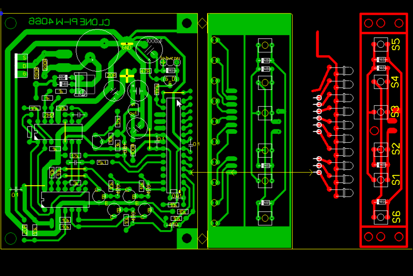 ()
()
This board has dimensions of 90x70mm and is designed both for a separate LED socket (in this case, you need to connect each LED to the microcircuit through a 510 Ohm resistor), and for LEDs located on the panel with buttons (and then just connect the ground of the main board to the ground of the socket through 510 ohm resistor).
Transistors 2N5551 can be replaced with S9014, KT503 or KT3102.
All of the above printed circuit boards are already mirrored, you just need to print.
After soldering, the scarf MUST be washed from the flux. Do not even try to assemble on the circuit board, it will either not work, or it will be terribly buggy.
microcontroller firmware
To upload the firmware to ATMEG you will need a programmer. The two most primitive circuits designed specifically for the ATmega8 are shown in. You can choose any of them.
PonyProg
If you decide to flash using the PonyProg program, then you need to set the fuses as in the picture: 
When using another program, you may need to set these checkboxes inversely (that is, where the checkbox is in the picture, it should not be set, on the contrary). If, after reading the bits in your program, there is no checkmark next to "SPIEN", then all other bits must be set directly opposite to the screenshot. The SPIEN bit itself MUST NOT be changed under any circumstances.
Gromov programmer
After connecting the programmer (how to do this, we read in the same article), first of all we check whether the fuse bits are read. If everything is ok, set the bits as follows: 
Everything is carefully checked and recorded. This completes the programming of the microcontroller.
What firmware is better?
All existing this moment firmware versions. In my opinion (and many diggers will agree with me), firmware 1.2.2m turned out to be the most successful. She absorbed all the best from 1.2.1 and 1.2.4, and in the end it turned out just a fairy tale! Better, in my opinion, can not be imagined.
As for me, it is more stable, it gives very few false positives (you can go for a long time without hearing a single beep). I also really like the overload alarm - a loud low-frequency sound that is heard after the last 10th LED has been lit. The signal allows you to very accurately locate the target. This sound, as it were, says that the target is here, right under the coil! The reset in firmware 1.2.2m was made silent, which is also a definite plus in my opinion.
I think that with this version, the depth sensors will work stably.
Trial run (SMOKE test)
Since the manufacture of the body, sensor and rod is the most time-consuming task, it is best to check the functionality of the metal detector board immediately after the controller is flashed.
The coil does not need to be connected. You just need to solder the socket with LEDs and buttons and do not forget about the squeaker.
After applying power, the Clone initiates some self-diagnosis, which manifests itself in the alternate ignition of the LEDs and the generation of sounds of different tones. If everything is assembled and flashed correctly, then it should be something like this:
Reaction of the working circuit to pressing the reset button:
In some firmwares (for example, 1.2.2), when resetting the Clone, there is no sound.
If the box is silent, look for errors in the circuit, faulty parts, or check the performance of the Atmega. Typical causes of inoperability are given at the end of the article.
Button assignment
The purpose of the buttons does not depend on the firmware version.
- Barrier buttons: S1 - minus, S2 - plus. The barrier raises the threshold at which the signal from the analog part of the device is perceived as the presence of a target. Thus, by increasing the barrier, we raise the metal detector's response threshold to the metal, thereby lowering the sensitivity. In other words, the higher we set the barrier (more LEDs) - the lower the feel for the metal and the less false positives. The set value of the barrier is remembered even after the power is turned off. The value of the barrier does not affect the value guard interval (GID). The guard interval is set automatically each time the power is turned on (the microcontroller calculates the RFG depending on the circuit setting, coil parameters and the environment). The RFG value can be changed manually in the settings mode using the barrier adjustment buttons, but this makes no sense and in practice no one ever does this. After the power is turned off, the RFG value is not saved.
- Volume: S3 - minus, S4 - plus (maximum level - 7). In the settings mode, these buttons set the minimum allowable supply voltage (from 7.5 to 11V, step - 0.5, by default it is 8 Volts). If the voltage drops below the set level, the device will continue to work, but a characteristic low-frequency signal will sound every 15 seconds.
- Button S5 - entrance to settings mode(not in all firmware versions). If you are not making a metal detector for yourself, then it is better not to set this button at all. In order not to tempt once again.
- Button S6 - reset. It is used for self-excitation, freezing of the device - in which case, press reset and continue the search. Pressing the reset button just clears the microcontroller's registers, stacks, flags, and other internal processor kitchen (I'm not very good at this), which allows it to continue normal operation. The reset button has no effect on the guard interval calculated when the device is turned on, the set barrier and the volume level.
Sensor (coil)
A huge advantage of this metal detector is the ease of manufacture of the sensor. In the simplest case, it is 27 turns of wire with a diameter of 0.6-0.8 mm wound in bulk on a mandrel with a diameter of 21 cm.
For this MD, the "basket" coil from KASHCHEY Ø22cm is very well suited.
The “sniper” coil allows you to localize the target very accurately: diameter 18.5 cm, 23 turns with 0.5 mm wire.
To find out the number of turns for coils of a different diameter, you can follow the table: 
There are ready-made forms for coils on sale, in which sensors with a diameter of 19 or 26 cm can be placed. Two coils cannot be placed in one form at the same time, so wind the one that is 26 cm. This is approximately 21-23 turns of wire 0.7 ... 0.8 mm. The total resistance should be between 0.7 and 2 ohms. 
For deep search, you can build a frame with sides of 70x70cm or even a meter per meter (16 turns of wire are enough). But based on experience, I can say that with such a sensor, in principle, you will not gain anything. It also catches small (relative) ones, and it is VERY inconvenient to carry it. It is suitable only for work on an open field, and then it will be necessary to raise it above the ground by 70 centimeters - and with such distances you will miss a lot of interesting things. Although for those who are going to catch tanks, it will do. 
Who wants more, make a sensor Ø30-35 cm, 20 turns. With such a coil, having gained a little experience, it will be possible to look for small things, and coarse grains, by changing the distance between the sensor and the ground. And forget about deep frames, it's crap.
An elliptical coil for an impulse, this is nothing more than a show-off. There is a lot of fuss in manufacturing, and the expansion of the target capture area is not that big (5-7 cm). But if you already have a suitable frame - then ok.
By the way, a good frame for winding can be made, for example, from a coil from a semi-automatic welding machine. Cut off all unnecessary, remove the partitions and you get a very durable case with a diameter of 24.5 cm. 
Whoever wants to experiment can wind a "planar" coil (like Chance's). The smell turns out to be terrible: the sewer manhole is 170 cm. But the truth does not react weakly to the ground either, you have to coarsen the smell. So the end result will not be much different from a ring-shaped sensor. 
Out of curiosity, I tried a coil like the one in the picture above - it works great. Frame thickness ~4 mm. It is easier to wind it than a truly planar one: 
A basket-type coil will also work (http://www.metdet.ru/Sensor_K1.htm): 
With it, the feel is a little higher (a couple of centimeters), but it also catches more interference.
You can also use such a coil as in the photo below, but, believe me, this "beard" is not worth such an effort. The ring is wound much easier, and the indicators are almost the same. 
In short, there are many suitable options for manufacturing sensors, but nothing is simpler than a conventional ring. And the difference in the detection depth is either insignificant, or is leveled by false alarms from the ground.
There is also an interesting option - the usual "double ring" (or double-circuit coil). Two coils are wound - 15 turns on a mandrel about 12 cm and 12 turns on a mandrel about 23 cm. One is located inside the other, connected in series and connected to the device. The idea is that a small coil will catch small targets, and a large coil will catch large targets at a good depth. 
My advice to you: first, wind the sensor on a 21 cm frame, with a wire from 0.65 mm, seal it all properly with bauxite and you will have an excellent coil that meets the requirements of even the most spoiled digger. 
Glue the resulting coil between sheets of plywood and you're done: 

And only then, when you gain experience, make a basket oval sensor and add 1-2 cm of depth with it.
Whoever has problems with the winding wire, wind it with aluminum (1mm in diameter). Only the ends of the coil must be soldered to copper pins. Twists are not allowed. Either do not use acidic flux, or rinse it off very carefully.
Impregnation / potting
Before pouring in the form, you need to make a small frame to tie together the coil itself, ears, cable entry. Then all this is wrapped with fiberglass or just a medical bandage and poured. I fill with epoxy. It is highly desirable to choose the shape in such a way that the resin does not flow much, otherwise, when the sensor hits a tree / stone, it may burst or crack. I use about 150-200 grams of resin per coil.
Forms for pouring are made from anything - bucket lids, Teflon-coated pans, frisbee plates, someone even mills molds from thick plexiglass. Some are simply wrapped with fiberglass and impregnated with resin. A friend of mine cuts out a form from drywall, and after hardening, throws the whole structure into the water. After a couple of hours, the entire drywall turns into pumpkin porridge and falls off. What remains is a clean coil.
By the way, polyurethane foam is great for covering any cracks and joints. You just need to know one trick: we release a little foam into the water, mix it right in the water, and as soon as it settles (extinguished) - you take the resulting mass and use it for your own purposes. The material turns out super-duper: moderately hard, not porous, easily skinned, cut. In general, you can sculpt anything. Dries instantly - 20-30 minutes. 
Epoxy can be mixed with flour to make it opaque. And another amazing result is the reinforcement of the resin with microspheres - the sensor with them turns out to be light, durable and less affected by temperature. Microspheres are such small granules, there are glass and plastic. They are so small that they look like powder: 
reel cannot be shielded- This is a pulse device, and not balanced or on beats. Here is a completely different principle of operation.
From personal experience: for me, a sensor in the form of a solid pancake is better than one with a jumper in the middle. Grass constantly gets into these slots and gets in the way. And a solid pancake calmly glides over it, without clinging to anything. But the pancake is slightly heavier, so see what is more important to you - comfort or light weight.
The wire from the block to the coil is ordinary, unshielded, with good insulation and a cross section of about 0.75 square (for example, you can cut it off from a neighbor's floor lamp or vacuum cleaner). Wires from high-quality audio systems, in transparent insulation, are well suited. 
The cable for the impulse, the shorter - the better, 3-4 turns are enough for a fully extended rod.
As for attaching the coil to the bar - make it as powerful as possible! From my experience in repairing MD, I can responsibly state that broken off "ears" on the sensor are the most common breakdown that is handled. They break everything and everyone (the company and not the company). Making their way through the kusheri, they step on the sensor and say hello to the family. The factory bar tends to hold up, but the ears don't. A classic of the genre - one ear is completely missing, the second is broken by 50%.
Thick fiberglass or high-impact polystyrene with a thickness of at least 3-4 mm is well suited for the ears. You can cut them out of the toilet lid (they are very thick).
By the way, I do not advise you to make a barbell in the form of just a straight stick, as in the photo above - this is not very convenient and fatigue will not take long. It’s better to immediately make a proven S-shaped forearm grip: 
The armrest is a must (unless, of course, you want to rest under the bushes with aching pain in your arm in a couple of hours). The ideal armrest is metal. The plastic one will break sooner or later, hundreds of treasure hunters have already seen this. 
A few words about the design of the block itself
Do not take too high a body, a height of 36-50 mm is enough. And it will look prettier. It is better to take the case without ventilation slots so that it is airtight. And then after a couple of cops there will be anything inside: dirt, water, grass, dust, flies, ants, spiders, mice and bugs are different. And all this living creatures will constantly crowd and interfere there (checked personally on a detective).
In a box with dimensions of 150x88x47, in addition to the board, a cassette for 8 fingers is placed. The D150Ak box (91x147x36) fits perfectly. 
Small holes for the speaker (or piezo buzzer) are best made from below, so that sudden rain does not penetrate through these holes and flood the membrane.
For my latest Clone, I adapted a 120x97x40mm aluminum case. Three got in without a problem. lithium battery 18650 (from old laptop batteries, bought for 100 rubles / piece), the metal detector board itself, on which I also placed three simple chargers on the TIP41 transistor (taken). 
Thus, everything turned out to be compact, in a single case and no extra wires. I stuck a coil and went to dig!
Food
Batteries or AA batteries in the amount of 8 pcs are suitable for power supply. People using this device on such batteries wrote that they last for 5-7 hours of operation. A set of 8 AAs is enough for 10 hours of active searching.
I used 4 Li-Ion batteries from old ones in one of the devices cell phones, still lay idle.
I know that some even powered from an 18-volt battery from a screwdriver. And it worked. The main thing here is to make sure that all capacitors are rated no lower than 25V.
The main requirement is that the power source must produce 160-180 mA without a drawdown (this is the maximum consumption of the device when the LEDs are on and a metal object is nearby). So any Krona or D-0.125 tablets will not work !!!
With a weak power supply, the device will not work. For reference, the amplitude of the pulse in the coil reaches 200 volts, and the current is 20 amperes. So everything is serious.
The ideal option is 3 or 4 18650 batteries and something like this box for them: 
If you plan to use some kind of heavier battery (for example, lead or gel from an uninterruptible power supply), then it is advisable to consider placing it under the armrest. This will contribute to a better balance of the entire structure. 
Setting up the MD Clone PI-W
Setting up a working device consists in balancing a bridge consisting of a sensor and resistors R1, R3, R6, R9 and R7, R8, R11. This is done by selecting the resistance trimmer R7.
There are two tuning options - by ear or using an oscilloscope.
Tuning by ear

At each found position of the tuning resistor, we press the reset button and check what the sensitivity is. A good result in the air can be considered 22-25 cm for the Soviet five kopecks. You need to check not "by eye", but with the help of a wooden rail with risks applied on it.
If the specified sensitivity is reached, the setup of the metal detector can be considered complete.
Due to the high sensitivity of the analog part of the device, I strongly recommend that you make the final adjustment somewhere in nature, away from power lines and industrial interference. For example, go to the field, find a lonely tree there, hang the coil on a branch, and even then you can turn R7.
We never touch this trimmer again, and generally forget about its existence. If it is necessary to roughen up the feel (for example, to "rebuild from the ground"), we do this with the help of the barrier buttons.
Tuning with an oscilloscope
The bottom line is to use R7 to achieve a flat horizontal section of the waveform between the pulses on the pin. 1 op amp chip TL074: 
At this stage, it sometimes turns out that the resistance of the resistor R7 is not enough to fully balance the Clone. Then you also have to select the resistor R8.
Setting must be accompanied by control of the sensitivity of the device! The fact is that a flat section of the oscillogram is achieved in a fairly wide range of resistances R7, so we observe the behavior of the device: turn it on / off, bring coins, look for the most suitable position for the trimmer.
Set the minimum supply voltage
By default, the minimum supply voltage at which the device turns on the low battery alarm is set to 8 Volts. If you need something else (for example, so as not to ruin the batteries), then this value can be set manually through the service menu.
We enter the settings by pressing the S5 button. A sign of being in the settings mode is the glow of the last LED (VD13). Use the volume buttons to set the desired voltage value. The minimum allowable voltage is indicated by LEDs from the first to the tenth in half-volt increments - from 7.5 to 11V.
If during the operation of the device the supply voltage drops below set value, the metal detector continues to work, but every few seconds it gives out a double low sound. This is a signal that it is time to get the second set of batteries.
The supply voltage sensor for the controller is the divider R22, R23.
guard interval
Any impulsnik has such a thing as a guard interval (GID). This is the time interval between the moment the pulse is generated and the moment the reflected signal is received. 
In this DM, the value of the guard interval is selected automatically when the device is turned on (this is when the LEDs start to go out one by one). It can also be set manually via the menu. After the power is turned off, the value is not remembered. Therefore, it is very important that when the device is turned on, there are no metal objects near the sensor. In practice, this is achieved by simply lifting the coil into the air overhead.
If you turn on the metal detector near, for example, a shovel, then the device will set the value of the RFG for the given operating conditions and will not notice targets at close range, the reflection from which will be less than from this shovel. The approximate value of the guard interval can be determined by how many LEDs go out at the same time at the end of the test after switching on - the more, the more RFG.
Although, if you are only interested in the largest targets, the device can be turned on right on the ground. Large mines, shells, factories and ships will still ring.
Now as for the button to enter the setup mode. It's no secret that some people remove it altogether.
I agree that this button is almost never used, and few people understand why it is needed at all. Therefore, if you make a device for someone who does not really understand the principle of operation of impulse switches, then it is better to remove the button from harm's way.
Personally, I sometimes set the guard interval to plus, thereby cutting the scent into smallness. It would seem why this is needed when there is a barrier? It turns out everything is not so simple. The barrier really helps with ground balancing. But the increase in the guard interval manifests itself somewhat differently. This can only be felt when searching, although during room tests it may seem that this function is not needed or even harmful - because it lowers the sensitivity of the device.
I'll try to explain based on my own experience. In short, from every metal object lying in the ground, a gallo (aura) spreads from the mineralized soil, so even a small nail can radiate like a borscht pan. And the guard interval function helps to rebuild (although in some cases not completely) from such rotten small things and focus on finding larger items. In practice, proper use of the guard interval allows you to dig less idle. Something like this...
What to do if nothing works
Most likely, this will not happen to you, but even if it does, do not panic! It's OK.
First of all, check the current consumption - it should be in the range of 60-80 mA. If you bring a large metal object to the coil, the current should increase to 150-170 mA. If the currents are too high, we immediately turn everything off and look for a short circuit on the board, look at which elements are very hot, find out the reason.
If everything is in order with the currents, make sure that the controller is flashed correctly. A non-flashed controller will blink the first LED, as if hinting that it is empty.
When turned on, a properly programmed controller, regardless of the operability of the analog part of the circuit, should turn on the LED illumination and sing in every way. If the LEDs do not light up, check the power supply to the MK, the correct installation of the LEDs.
If there is no sound, the pinout of the field-effect transistor VT2 may be confused. Be aware that BSN304 and BSN304A have different pin assignments!
If everything is in order, bring the magnet close to the coil - you should feel how it itches and vibrates. Not much, of course, but noticeable. If there is a buzz, then the controller, the key chip and the powerful IRF740 field effect transistor are working. Already good.
If the magnet does not buzz, touch the field worker - it should not get very hot. If it heats up, it is possible either a short circuit in the coil, or it is constantly open (there is already a suspicion of a key chip or controller).
If R12 constantly burns out - either a short circuit somewhere, or C1 was inserted incorrectly, or the controller itself is faulty, or they forgot to insert a key chip (444, KN or 4066) into the socket - one of its elements acts as a field driver.
I repeat that the device can be turned on without a sensor - first one LED will light up, then the entire scale of 10 pieces will immediately light up, and then they will all go out at once and silence will come. At least on firmware 1.2.2, everything happens that way. On firmware 1.0.1, LEDs without a sensor will go out one at a time. And if it doesn’t work for you, then the microcontroller does not work: check the power circuits and firmware. When checking the firmware, pay special attention to the configuration or fuse bits (read them and compare them with the picture I gave above).
If, when the device is turned on, sound and light illumination is observed, the coil makes the magnet “buzz”, but there is no reaction to the metal and adjusting the trimmer R7 does not lead to anything, carefully check the compliance of your board circuit diagram. Somewhere they hung snot when soldering, forgot to draw a path, etc. Pay special attention to the resistor values in the TL074 harness - call them directly on the board.
The lack of reaction to metal can be if, when turned on, the coil was near a large metal object (battery, chair frame, contents of desk drawers, etc.)
Make sure that the flux does not flow into the socket and does not break the contact (if you use sockets, take those with gold-plated collet clips - in principle, such a problem is excluded in them). If the error cannot be found, successively replace the key chip first, then the TL074 OU.
For a working device with a connected sensor and no metals nearby, the outputs of the TL074 OU should have the following voltages:
- Pins 5, 10 - voltage equal to Uref 4.5 - 4.9 V. These voltages come directly from the TL431 stabilizer. If there is a strong deviation, check the divider R19, R20.
- On a balanced op-amp, the same voltage (with a difference of hundredths of a volt) should also be on pins 1, 2, 3, 5, 7 and 14. With serviceable parts, but an unbalanced op-amp, the voltages may differ slightly - by 0.2 ... 0.5 Volts (they will fall into place when balancing with a trimmer). If the torsion of the resistor R7 does not lead to a change in the voltage at pin 7 of the OU, the trimmer must be replaced.
- The voltage at pins 12 and 13 should be the same and be slightly less than the voltage of the power source (about 0.6-0.7V). If this is not the case, check the trimmer and the entire input circuit.
- Output voltage 8 and 9 should be approximately equal to half the voltage of the power supply and depends on the quality of the op-amp and the correct binding. The more meticulousness you put into picking up the parts, the closer the voltage will be to half of the supply. As a rule, it is equal to 4.5 ... 7V. The closer to the pin. 8 voltage to half the voltage of the power supply, the better the copy of the op-amp you got.
- Output voltage 6 op amps - about 3 ... 5 volts. It is difficult to measure with a digital device, it is desirable to have a pointer voltmeter.
Here is a diagram of the voltages taken from the working device at a supply voltage of 10.7V (the batteries have already sat down slightly): 
The most common beginner mistakes:
- they stuck the chips in the wrong end;
- when flashing, they were smart with bits of the MK configuration and put him to sleep forever and ever;
- Short circuit in the search coil (low sensitivity, high current consumption);
- turned the trimmer's head;
- there is no contact (bad contact) in the cable connector. Solution: temporarily (or better permanently) solder the sensor directly. Or use a high-quality connector with reliable gold-plated contacts;
- the board is dirty, the flux is not washed, acid flux was used when soldering (the latter is generally unacceptable under any circumstances);
- poor-quality soldering, false soldering, snot on the board.
Causes of all sorts of glitches:
Check everything. Check the board ten times, call or replace questionable elements. The circuit is quite simple and the malfunction is 100% in front of your eyes. If you show a little attention and patience, you will find it.
If the device works, but has low sensitivity, and the setting does not help, then you may have come across a "dumb" TL074 chip. Try replacing. In my practice, different microcircuits from the same batch gave a significantly different feel (almost twice!).
The gain of the first stage of the op amp is 7 and is set by the resistor R11. The gain of the second stage is about 10, set by the resistor R15. By changing R15, you can slightly raise or, conversely, coarsen the feel of the device. I know craftsmen who even put a variable resistor instead of R15 and put it on the front panel (like sensitivity adjustment!).
Lately there has been an increase in marriage reports among TL074s. If you can't seem to find the problem, this might be the issue.
If there is a suspicion of a defective TL074 chip, try to take it from old equipment, or buy it in another store from a different batch, or use analogues: TL064, TL084, TLC274, LF347, MCP604, MC34004P, TA75074P, ECG859. You can also pre-seed the signet for two dual op-amps (for example, TL072 or TL082).
Or, as an option, you can try to plug 074 into the board in smd-version (among them, so far no marriage has been noticed). 
Impressions from the device
I love this metal detector! I gave some here to the diggers, so they already goggled their eyes: they rang the firing cell with the branded "Fisher", it showed nothing, and my Clone lit the third diode. They dug for 20 minutes, the soil was heavy, the stones were on top. As a result, they raised three sleeves from a three-inch gun from a depth of at least 40 cm!
And once one of my acquaintances wanted to wander with a metal detector outside our village and returned an hour later with a gilded button. He says that he dug right on the side of the road at a depth of one bayonet. He said that the device was screaming like a cut.
Judging by the numerous reviews, a well-tuned Clone has about twice as much flair for coarse stuff than an ICQ 250 with a native coil. True, ICQ has a discrepancy, it will be possible to find more flower gardens (if this flower garden still remains in the ground at all), it’s good to tinker with it on the beach in the sand. And so, ACE-250 is a device entry level, children's toy can be said. As the owner of ICQ in the past, I can add that if it suited me in everything, I would not get the soldering iron out of the closet.
By the way, I recently tested my Elephant on the Black Sea. There were no problems, it works great on sea water. The main thing is that I'm walking along the beach with a clone, and my colleague with a minilab for a piece of bucks, and the result is the same for everyone. In general, this device was originally conceived by the author as an option for underwater search.
A small increase in the feel has been seen with coils starting at 30 cm. But with them it becomes more difficult to localize the target. In other words, when digging a small object, you can miss the hole - you dig and dig, but it still doesn’t exist, and the Clone keeps ringing and ringing. You dig and imagine a super-treasure at a great depth, but in the end it turns out that a beer cork rang at a depth of 15 cm a little to the side.
By the way, Clone Pi-W works in static mode. This allows you to more accurately localize the target. Only in latest firmware 1.2.5 implemented a dynamic search mode. In my opinion, static is much more convenient.
When searching in heavily littered areas, it is enough to raise the coil above the ground (by 20 centimeters). And all your krupnyak. And not only krupnyak.
The Clone has also been seen choking other metal detectors with its static. So you have to run away.
conclusions
Among homemade impulses, there are no equals to the Clone yet. Going for ferrous metal or going to war is the very fire! To search for coins and the like - it will also do, you just have to dig more. See, for example, what we managed to dig up: 
Apparently, this is the Libavo-Romenskaya railway plaque of 1874.
Well, below are my very first finds by Clone (I saved them as a keepsake): 
In general, if you need a balancer with a discriminator, then I recommend trying to assemble and configure a digital Quasar or an analog Terminator. Although, for example, the same "Anker" will be much longer-range, and the "Spectrum" will be more informative ... It's up to you!

Clone Pi AVR this is a simplified and improved version of the metal detector popular with radio amateurs. Since in the manufacture of the Clone PI metal detector, many had difficulties with the purchase of an ADC, in the new version of the Clone PI metal detector AVR, the Peak controller and an external ADC were replaced by an affordable AVR microcontroller with an internal ADC Atmega8.
Scheme of the metal detector Clone PI AVR

As well as the Clone PI AVR circuit with the specified DC voltages
 On the Internet, there are several options for breeding a printed circuit board for a Clone Pi AVR metal detector. Below is a photo of a quite decent version of the PCB.
 In this archive you can download: a printed circuit board in *.lay format, a diagram, firmware and photos of the stages of manufacturing a metal detector board.
To flash the microcontroller, the configuration bits must be arranged as follows:

Metal detector Clone PI AVR has an average level of complexity manufacturing, due to the presence in the metal detector circuit, of a programmable microcontroller. But otherwise, its manufacture should not cause any special difficulties.
Coil for metal detector Clone PI AVR
With the Clone PI AVR metal detector, you can use coils from the Tracker and Koschei pulse metal detectors, as well as large depth frames.
The most versatile coil diameters are 20-30 cm. Such coils will have a detection depth of 1 - 1.5 meters and will remain sensitive to small metal objects (coins, jewelry, etc.).
For the manufacture of a universal search coil, you need to wind 23-24 turns of winding enamel wire with a diameter of 0.7-0.8mm on a mandrel 26-27 cm. As a mandrel, you can use a saucepan of a suitable diameter, or make a mandrel as in the photo below:

To make a mandrel, we take a sheet of plywood or chipboard. On it, with the help of a compass, we draw a circle with the diameter we need. Then we take screws or self-tapping screws, we put cambric on them. We screw the screws with cambrics around the perimeter of our circle, and we get a mandrel for winding the coil.
The coil is wound in bulk. Then the turns are tightly wound together, with adhesive tape, or electrical tape. We solder the wire 2 * 0.75 mm in insulation to the ends of the winding.

We connect our coil to the board of the Clone Pi AVR metal detector (It is better to use a connector for connection) and check its performance. Such a coil is suitable for testing and experimentation, but for real work, it should be protected from shock, moisture, etc.
To do this, the coil must be fixed in a suitable plastic case. In our designs, we use such a universal case.
 The coil is fixed inside the body with hot glue, and then the coil body is sealed with dichloroethane, or twisted with stainless steel screws.
To obtain an underwater coil, it is better to fill the body with epoxy. This will reduce its buoyancy and prevent water from entering the inside of the hull.

Firmware for metal detector Clone PI AVR:
- Firmware version 1.7.3 for ATmega8 - CPI_PRG_173_AVR
- Firmware version 1.7.3A for ATmega8, with modified auto-ground algorithm - CPI_PRG_173a_AVR
- Firmware version 1.8.0 for the controller ATmega8- CPI_PRG_180_AVR Changes:
- The volume of the button sounds has been adjusted to match the main volume.
- Ground adjust now works in 3 modes - adaptive, fixing and off(static).
- Guard interval can now be picked up when enabled ( auto), use the stored value ( last), or be selected by the user forcibly in the range 2 … 80 .
- Added option volume raise, which allows you to reduce the volume at the beginning of the scale (with weak responses). This improves the stability of the circuit at a low threshold.
- Removed double power mode, which showed its practical uselessness.
- When the backlight is on, the letter “L” (Light) is displayed on the indicator.
- Firmware version 1.8.1 for the controller ATmega8, bugs fixed in firmware and power consumption reduced – CPI_PRG_181_AVR
Conclusion: Clone PI AVR metal detector This is a proven and popular metal detector among radio amateurs and search engines. It has a search depth comparable to factory metal detectors and a completely open circuit and firmware for its manufacture. To shortcomings metal detector should be attributed to excessive power consumption.
Video of the launch of the Clone PI AVR metal detector assembled by oneself, and the possibility of setting it up:
Materials used in the writing of this article:
- Developer site - http://fandy.hut2.ru
- And this site - http://metdet.ucoz.ua/publ/metalloiskatel_klon/1-1-0-13
- And also a forum - http://md4u.ru/viewtopic.php?f=5&t=660 - here you can ask questions about self-assembly of the metal detector.
(high quality workmanship)
Clone PI AVR- modern impulse microcontroller metal detector with LCD screen and sound indication. The principle of operation is based on the excitation of pulsed eddy currents in a metal object and the measurement of the secondary electromagnetic field that these currents induce.
Able to work with coils of different diameters (coils up to 120 - 150 cm in diameter) automatically adjusting to work with them. The metal detector can be effectively used to search for any metal objects, up to 4 meters in depth, based on the installed coil. It has good sensitivity to small objects.
The Clone PI AVR metal detector has a display backlight for night time operation. There is a detuning from the ground (depending on humidity and the content of metallic impurities). In the device settings there is also an indication of the battery power (when the set level is reached, the metal detector automatically turns off, which is important when working on battery power). There is a barrier, a sensitivity threshold at which the metal detector is triggered by a metal object.
Thanks to the microcontroller (processor) used in the clone pi avr metal detector circuit, the device is fully automatic, has an intuitive menu that even any beginner will master it very quickly. A worthy competitor to industrial metal detectors, but the cost is much cheaper. The disadvantage of the metal detector is the lack of selectivity (does not distinguish between ferrous and non-ferrous metals)
Clone PI AVR is a somewhat simplified version of the Clone PI pulse metal detector. In turn, Clone PI is a slightly revised version of the Tracker PI pulse metal detector - the commercial version - Koschei PI. Therefore the name Clone.
| Characteristics of the impulse microprocessor-based metal detector Clone PI AVR | |
| Principle of operation | PI (Pulse) |
| Selectivity of metals | Not |
| Food | Two lithium 3.7V 2200mA |
| Instrument weight | 1300 grams |
| Height | 105 cm |
| Control | Push-button (4 kn.) |
| Menu settings | Ground balancing, volume control, display backlight control, search sensor "guard interval" control, installation automatic shutdown device, with a certain battery discharge |
| Display | LCD indicator 2 lines 16 characters |
| Voice acting | Adjustable (speaker) |
| Firmware | V 1.8.1 with Russian translation (or English) |
| Purpose of use | 5-point evaluation of the device | Notes |
| Search for coins, rings and other valuable items made of gold and other non-ferrous metals | 4 | Does not distinguish between metals, but has very good sensitivity to small objects (coins, rings, chains) |
| Search for objects of military archeology (walking in the war), non-ferrous and ferrous metals | 5 | Fits perfectly, finds a soldier's helmet (coil 24 cm in diameter) at a depth of 55 cm, larger objects up to 140 cm |
| Search for non-ferrous and ferrous metals of large sizes, collection of scrap metal | 5 | Fits perfectly, able to find metals at great depths |
| If desired, and with the appropriate knowledge of electronics, the device can be made independently! The author of the device is Andrey Fedorov, he is Andy_F. Author's homepage: |


