Homemade installation of a tweeter on mb 830 p. Do-it-yourself sound piezo emitter
Creating circuits for beginners is indeed a very difficult task. Every time you have to find a compromise between reliability, simplicity, repeatability, "not to be killed" and, at the same time, it (the scheme) must be interesting, able to lead and be informative. It is impossible to develop a device that will equally meet all these qualities in the same way for different age groups of students. And the younger they are, the harder it is to do it! In this article, I want to talk about designs that four graders repeat with pleasure. Yes, there is little novelty in circuit solutions (to say the least - no). But there is a system and reliability of structures, their high repeatability and low cost. And I will not bother with theory, because for a fourth grade student to know: this is a resistor, this is a capacitor, and this is a transistor and it has three legs (!!!) is already a great achievement. For the same reason, I will not give the PCB layout, since the etching of boards at this age it is forbidden according to the elementary rules of safety and common sense. Installation is carried out by a hinged method on a piece of cardboard under the guidance of a teacher or parent.
The “heart” of all the devices I am considering will be the simplest sound generator, made on a single-junction transistor KT117, and, through simple upgrades, we will get different consumer qualities.
Video of work:
Often such tweeters are called "mosquito repeller", but who would act as a voluntary donor and in practice would prove the effectiveness (not efficiency) of such devices? Personally, I prefer to use chemicals. But you need to somehow encourage the child to repeat the scheme! And so ... WE Frightened the mosquito!
It's just not fun to eat. Consistently with the battery, we install the key model and simulate the operation of the telegraph. And, be afraid of school teachers, it squeaks disgustingly, the tone is high, the location of the generator in space is hard to localize by ear. But when to brag about your design in front of peers if not in the classroom?
This scheme is easy to transform into a sound beacon. To do this, it is often recommended to power the entire generator through a flashing LED. This is not entirely true. Yes, the circuit will work, but the closed LED (it does not glow) still passes current through itself, since its p-n junctions included in the forward direction. The generation frequency of the circuit also depends on the supply voltage, as a result of which the sound is torn - a loud high tone alternates with a quiet low tone. This disadvantage can be eliminated by introducing control of the flashing LED on the second base of the transistor.

Video of work:
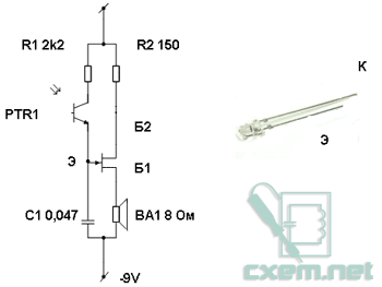
Another interesting transformation of the original scheme is the introduction of the dependence of the tone of the generator on the illumination. To do this, a PTR1 phototransistor should be introduced into the circuit, controlling a unijunction transistor from the emitter side with it. The generator squeaks even more disgustingly, but how much joy the child is caused by the fact that the sound is completely different at the window and inside the room!
Video of work:
And, of course, a two-tone siren, but how without it? Not a single police (police) car can do without it! To organize two-tone sounding, we introduce control of a unijunction transistor along the emitter using, again, a blinking LED. This design will be useful to insert into a toy car.

Video of work:
If you want to build a multi-tone automatic sound effects machine, then you need to use a three-color flashing diode as a control LED, or turn on three different diodes with different glows (red, blue, green as it is done). If you want to increase the sound volume, you must use any audio frequency amplifier, for this the speaker must be changed to a resistor with a resistance of 100 Ohms and a signal for ULF must be removed from it.
The schemes I have considered allow stimulating younger students to study the very basics of radio electronics, can be useful in the system of additional education, do not contain a large number details and do not cause difficulties in their repetition.
Herself scheme represents the simplest sound frequency generator (you can say a buzzer) and is assembled on only four parts:
How the tweeter circuit works
R1 sets the offset to the base VT1. And with the help of C1, Feedback. The speaker is the load VT2. The sound frequency can be adjusted by selecting capacitor C1
Necessary radio components for assembling a tweeter
1. Two transistors. It is best to use a complementary pair (let me remind you that transistors with the same parameters but different conductivity are called complementary). Almost any will do: from the old Soviet ones: KT315 and KT361, for example, from imported and inexpensive 2SA1015 and 2SC1815.
2. Speaker. You can use absolutely anyone: from a Chinese player, from an old tape recorder, or just an earpiece.
3. Capacitor: Absolutely any with a capacity ranging from 10 to 100 nanoFarads.
If suddenly someone forgot how to determine the capacitance of a capacitor by its digital code, then you can look into the reference materials section: there is a separate section Digital Capacitor Code
4. Voltage source. You can use any battery: at least a 1.5V "finger" battery, at least a 9-volt "crown", there is no difference - only the power will change.
5. Resistor. Again, any type (you can even trim) with a resistance of 10 to 200 kOhm.
6. Switch. You can use any toggle switch, button.
Correctly assembled circuit no configuration is required and starts working immediately.
If suddenly it didn’t work, but well: come to our FORUM, we will figure out why (and even if it works, come anyway !!)
This ultrasonic squeaker is designed for those people who got noisy neighbors. But first things first. The device is a simple voltage converter based on a blocking generator. The emitter is a piezo head, you can get it from a calculator, old wrist watch, a music box or a toy car, in general, I think that every house can find such a thing.
The transformer is a ferrite ring computer block power supply, other rings with almost any diameter will do, you can also use E-shaped transformers (ferrite) or ferrite cups. The transformer has two windings. Primary winding contains 40 turns with a tap from the middle, the wire diameter is also not critical from 0.1 to 0.8 mm, the turns are stretched throughout the ring. The secondary winding contains 30 turns of the same wire as the primary.

conclusions secondary winding directly connected to the piezo head, there is no connection polarity, it will work for anyone. Any low-frequency, reverse-conducting transistor such as KT819, KT805, KT829, KT817, KT814 and all imported analogues, you can also use field-effect transistors, which I do not advise you, since the current consumption of the device will be several times more than using bipolar transistors.

Also, to save energy, you can use high-frequency bipolar transistors of domestic production, for example, KT315, KT3102 or imported analogues C9014, 9016. As you can see, it is also not critical with transistors, you can literally put any that are at hand. A homemade ultrasonic tweeter can be powered by a 1.5 volt finger battery, a 3 volt lithium tablet, a battery from mobile phone with a voltage of 3.7 volts or a crown with a voltage of 9 volts. Option printed circuit board for the tweeter is shown below.

Now about the main thing, so what is the device? In order to understand the essence of the work, one has only to turn it on, it emits an irritable whistle that is barely audible, but very annoying. The main feature is that the neighbors will not be able to understand where the sound is coming from, but first you need to install this miracle in the house of a noisy and annoying neighbor. However, I hope that you can agree on a good one :)
Single transistor watchdog is the most simple circuit that even a preschooler can collect.
Are your properties often invaded without permission, while you are doing important business?)

It's time to forget these problems! I present to your attention the circuit of the watchdog on just ONE! Thanks to this scheme, you will be able to secure your home and take all necessary measures to eliminate the problems that have arisen in time!
Scheme and principle of operation
And here is the schematic

The pinout (pinout) of the KT815B transistor looks like this:

The principle of operation is very simple. When the security wire breaks, the buzzer starts beeping. A thin security wire can be pulled through the doorway.
To more accurately describe the operation of the circuit, it will look like this:
draw a diagram according to GOST for ease of perception
As long as we have a security wire intact, then in the circuit plus batteries - a 100 K resistor - the security wire will current flow. All current will flow through the guard wire, since its resistance is very small. Since all the current will flow through the wire, there won't be enough current to turn on the transistor. The transistor opens only when its voltage between the base and the emitter is 0.5-0.7 Volts.
But ... as soon as the security wire breaks, the voltage on the base immediately increases sharply, that is, it becomes more than 0.5-0.7 Volts and current begins to flow through the base-emitter. Since the current flows through the emitter base, the transistor turns on. And once it opens, it means that current begins to flow through the circuit plus batteries—buzzer—collector—emitter. As long as current flows through the buzzer, it yells like a scalded.
Assembly and work in practice
The circuit consists of a KT815 transistor with any letter. I took this one:

What's with the weird markings on the transistor? Previously, this is how Soviet transistors were designated. Experienced radio amateurs will immediately determine that this is a KT815B transistor. For beginners, I advise you to download the Transistor v1.0 program, which will allow you to easily identify Soviet transistors, even with color coding.
Here is an example of a transistor that I am using in a circuit:

The circuit also has a buzzer:

The buzzer is a sound emitter. When applying for it permanent voltage, it begins to squeak with a high-frequency unpleasant monotonous sound. I took it on Aliexpress for 0.7 bucks this link.
Buzzers are often confused with piezo emitters (below in the photo):
If we disassemble the buzzer, we will see on the scarf a simple circuit of a frequency generator made in SMD design, as well as the piezoelectric emitter itself, soldered copper wires to this scarf.

So if you take a buzzer in a radio store, make sure that the seller does not slip you an ordinary piezo emitter.
Instead of a buzzer, you can take a low-power light bulb or some kind of actuator that will be turned on through a relay. In this case, do not forget to protect the transistor by connecting a protective diode in parallel with the relay coil:

Well, here, in fact, is the video of the whole scheme. The orange wire is a type of security wiring.