How to distinguish the primary winding of a transformer from the secondary. What is the primary winding of a transformer? Related video
12.12.2017
Often you need to familiarize yourself in advance with the question of how to test the transformer. After all, if it fails or becomes unstable, it will be difficult to look for the cause of equipment failure. This simple electrical device can be diagnosed with a conventional multimeter. Let's see how to do it.
What is the equipment?
How to check the transformer if we do not know its design? Consider the principle of operation and varieties of simple equipment. Coils are applied to the magnetic core copper wire of a certain section so that there are conclusions for the supply winding and the secondary.
The transfer of energy to the secondary winding is carried out in a non-contact way. Here it becomes almost clear how to check the transformer. Similarly, the usual inductance is called with an ohmmeter. The turns form a resistance that can be measured. However, this method is applicable when the target value is known. After all, the resistance can change up or down as a result of heating. This is called interturn short circuit.
Such a device will no longer produce a reference voltage and current. The ohmmeter will only show an open circuit or a complete short circuit. For additional diagnostics, a short circuit test to the case is used with the same ohmmeter. How to test a transformer without knowing the winding leads?
Kinds
Transformers are divided into the following groups:
- Decreasing and raising.
- Power often serve to reduce the supply voltage.
- Current transformers for supplying a constant current to the consumer and holding it in a given range.
- Single and multi-phase.
- Welding purpose.
- Pulse.
Depending on the purpose of the equipment, the principle of approach to the question of how to check the transformer windings also changes. A multimeter can only ring small devices. Power machines already require a different approach to troubleshooting.
Call method
The ohmmeter diagnostic method will help with the question of how to check the power transformer. The resistance between the terminals of one winding begins to ring. This establishes the integrity of the conductor. Before this, the body is inspected for the absence of carbon deposits, sagging as a result of equipment heating.
Next, the current values \u200b\u200bare measured in Ohms and compared with the passport ones. If there are none, then additional diagnostics under voltage will be required. It is recommended to call each conclusion regarding metal case devices to which earth is connected.
Before taking measurements, disconnect all ends of the transformer. It is also recommended to disconnect them from the circuit for your own safety. They also check for the presence of an electronic circuit, which is often present in modern power models. It should also be soldered before testing.
Infinite resistance speaks of a whole isolation. Values of several kilo-ohms already raise suspicions about a breakdown on the case. It can also be due to accumulated dirt, dust or moisture in the air gaps of the device.
Under voltage
Energized tests are performed when the question is how to test a transformer for turn-to-turn faults. If we know the value of the supply voltage of the device for which the transformer is intended, then measure the idle value with a voltmeter. That is, the output wires are in the air.

If the voltage value differs from the nominal value, then conclusions are drawn about the interturn circuit in the windings. If crackling, sparking is heard during operation of the device, then it is better to turn off such a transformer immediately. He is defective. There are permissible deviations in measurements:
- For voltage, the values may differ by 20%.
- For resistance, the norm is a spread of values \u200b\u200bin 50% of the passport ones.
Measurement with an ammeter
Let's figure out how to check the current transformer. It is included in the chain: regular or actually made. It is important that the current value is not less than the nominal value. Measurements with an ammeter are carried out in the primary circuit and in the secondary.

The current in the primary circuit is compared with the secondary readings. More precisely, the first values are divided by those measured in the secondary winding. The transformation ratio should be taken from the reference book and compared with the calculations obtained. The results should be the same.
The current transformer must not be measured at no load. In this case, too high voltage may form on the secondary winding, which can damage the insulation. You should also observe the polarity of the connection, which will affect the operation of the entire connected circuit.
Typical malfunctions
Before checking the microwave transformer, we will give frequent types of breakdowns that can be fixed without a multimeter. Often, power supplies fail due to a short circuit. It is established by inspecting circuit boards, connectors, connections. Less common mechanical damage transformer housing and core.

Mechanical wear of the connections of the transformer leads occurs on moving machines. Large supply windings require constant cooling. In its absence, overheating and melting of the insulation is possible.
TDKS
Let's figure out how to check a pulse transformer. An ohmmeter can only establish the integrity of the windings. The operability of the device is established when connected to a circuit where a capacitor, a load and a sound generator are involved.

A pulse signal is sent to the primary winding in the range from 20 to 100 kHz. On the secondary winding, measurements are made with an oscilloscope. Establish the presence of pulse distortion. If they are absent, draw conclusions about a serviceable device.
Oscillogram distortions indicate damaged windings. It is not recommended to repair such devices yourself. They are set up in the laboratory. There are other verification schemes pulse transformers, where the presence of resonance on the windings is examined. Its absence indicates a faulty device.
You can also compare the shape of the pulses applied to the primary winding and exited from the secondary. The shape deviation also indicates a transformer malfunction.
Multiple windings
For resistance measurements, the ends are freed from electrical connections. Choose any output and measure all resistances relative to the rest. It is recommended to write down the values and mark the tested ends.

So we can determine the type of connection of the windings: with middle conclusions, without them, with a common connection point. More often found with a separate connection of the windings. Measurement can be done with only one of all the wires.
If there is a common point, then we measure the resistance between all available conductors. Two windings with a middle terminal will only make sense between the three wires. Several conclusions are found in transformers designed to work in several networks with a nominal value of 110 or 220 Volts.
Diagnostic nuances
The hum during transformer operation is normal if these are specific devices. Only sparking and crackling indicate a malfunction. Often the heating of the windings is the normal operation of the transformer. This is most often seen with step-down devices.
Resonance can be created when the transformer case vibrates. Then you just need to fix it with insulating material. The operation of the windings changes significantly with loose or dirty contacts. Most of the problems are solved by cleaning the metal to a shine and a new close-fitting of the conclusions.
When measuring voltage and current values, the ambient temperature, the magnitude and nature of the load should be taken into account. Supply voltage control is also required. Checking the frequency connection is mandatory. Asian and American appliances are rated at 60 Hz, resulting in lower output values.
Improper connection of the transformer may lead to a malfunction of the device. Never connect to windings constant pressure. The coils will quickly melt into otherwise. Accuracy in measurements and competent connection will help not only to find the cause of the breakdown, but also, possibly, to eliminate it in a painless way.
AT modern technology transformers are used quite often. These devices are used to increase or decrease the parameters of alternating electric current. The transformer consists of input and several (or at least one) output windings on a magnetic core. These are its main components. It happens that the device fails and it becomes necessary to repair or replace it. To determine whether the transformer is working, you can use a home multimeter on your own. So, how to check the transformer with a multimeter?
Fundamentals and principle of operation
The transformer itself belongs to the elementary devices, and the principle of its operation is based on the two-way transformation of the excited magnetic field. Tellingly, a magnetic field can only be induced using alternating current. If you have to work with a constant, you must first convert it.
Wound on the core of the device primary winding, to which an external alternating voltage with certain characteristics is supplied. It is followed by it or several secondary windings, in which an alternating voltage is induced. The transmission coefficient depends on the difference in the number of turns and the properties of the core.
Varieties
There are many types of transformers on the market today. Depending on the design chosen by the manufacturer, a variety of materials can be used. As for the shape, it is chosen solely from the convenience of placing the device in the appliance case. The design power is only affected by the configuration and material of the core. At the same time, the direction of the turns does not affect anything - the windings are wound both towards and away from each other. The only exception is the identical choice of direction if multiple secondary windings are used.

To test such a device, a conventional multimeter is sufficient, which will be used as a current transformer tester. No special devices are required.
Checking procedure
The transformer test begins with the definition of the windings. This can be done by marking on the device. The pin numbers should be indicated, as well as their type designations, which allows you to establish more information from the directories. In some cases, there are even explanatory drawings. If the transformer is installed in some kind of electronic device, then the electronic circuit diagram of this device, as well as a detailed specification, will be able to clarify the situation.

So, when all the conclusions are determined, the tester's turn comes. With it, you can install the two most common malfunctions - a short circuit (to the case or an adjacent winding) and a winding break. In the latter case, in the ohmmeter mode (resistance measurement), all windings call back in turn. If any of the measurements shows one, that is, infinite resistance, then there is a break.
There is an important nuance here. It is better to check on an analog device, since a digital one can give distorted readings due to high induction, which is especially true for windings with a large number turns.
When a short circuit to the case is being checked, one of the probes is connected to the winding terminal, while the second leads to the conclusions of all other windings and the case itself. To check the latter, you will first need to clean the place of contact from varnish and paint.
Interturn Fault Definition
Another common transformer failure is interturn short circuit. It is almost impossible to check a pulse transformer for such a malfunction with only a multimeter. However, if you involve the sense of smell, attentiveness and sharp vision, the problem may well be solved.
A bit of theory. The wire on the transformer is insulated exclusively with its own varnish coating. If there is an insulation breakdown, the resistance between adjacent turns remains, as a result of which the contact point heats up. That is why the first step is to carefully inspect the device for the appearance of streaks, blackening, burnt paper, swelling and burning smell.

Next, we try to determine the type of transformer. As soon as this is obtained, according to specialized reference books, you can see the resistance of its windings. Next, we switch the tester to the megohmmeter mode and begin to measure the insulation resistance of the windings. In this case, the pulse transformer tester is a regular multimeter.
Each measurement should be compared with that specified in the handbook. If there is a discrepancy of more than 50%, then the winding is faulty.
If the resistance of the windings is not indicated for one reason or another, other data must be given in the reference book: the type and cross section of the wire, as well as the number of turns. With their help, you can calculate the desired indicator yourself.
Checking household step-down devices
It should be noted the moment of checking classic step-down transformers with a tester-multimeter. You can find them in almost all power supplies that lower the input voltage from 220 volts to the output voltage of 5-30 volts.

The first step is to check the primary winding, which is supplied with a voltage of 220 volts. Signs of a primary winding failure:
- the slightest visibility of smoke;
- the smell of burning;
- crack.
In this case, you should immediately stop the experiment.
If everything is fine, you can proceed to the measurement on the secondary windings. You can only touch them with the contacts of the tester (probes). If the results obtained are less than the control ones by at least 20%, then the winding is faulty.
Unfortunately, it is possible to test such a current block only in cases where there is a completely similar and guaranteed working block, since it is from it that the control data will be collected. It should also be remembered that when working with indicators of the order of 10 ohms, some testers may distort the results.
No-load current measurement
If all tests have shown that the transformer is fully functional, it will not be superfluous to conduct another diagnosis - for the current of the idle transformer. Most often, it is equal to 0.1-0.15 of the nominal value, that is, the current under load.

For verification measuring device switch to ammeter mode. Important point! The multimeter should be connected short-circuited to the transformer under test.
This is important because during the supply of electricity to the transformer winding, the current strength increases up to several hundred times in comparison with the nominal one. After that, the tester probes open, and the indicators are displayed on the screen. It is they who display the value of the current without load, the no-load current. In a similar way, the indicators are measured on the secondary windings.
To measure the voltage, a rheostat is most often connected to the transformer. If it is not at hand, a tungsten spiral or a row of light bulbs can be used.
To increase the load, increase the number of light bulbs or reduce the number of turns of the spiral.
As you can see, no special tester is even required for verification. A normal multimeter will do. It is highly desirable to have at least an approximate understanding of the principles of operation and the design of transformers, but for a successful measurement, it is enough just to be able to switch the device to ohmmeter mode.
How to test a transformer?


The transformer, which translates as "Transformer", has entered our lives and is used everywhere in everyday life and industry. That is why it is necessary to be able to check the transformer for operability and serviceability in order to prevent breakage in the event of a failure. After all, the transformer is not so cheap. However, not every person knows how to check the current transformer on their own and often prefers to take it to the master, although the matter is not at all difficult.
Let's take a closer look at how you can check the transformer yourself.
How to test a transformer with a multimeter
The transformer works on simple principle. In one of its circuits, a magnetic field is created due to the alternating current, and in the second circuit, an electric current is created due to the magnetic field. This allows the two currents to be isolated inside the transformer. To test the transformer, you must:
- Find out if the transformer is damaged externally. Carefully inspect the transformer enclosure for dents, cracks, holes, or other damage. Often the transformer deteriorates from overheating. Perhaps you will see traces of melting or swelling on the case, then it does not make sense to look further at the transformer and it is better to take it in for repair.
- Examine the transformer windings. There must be clearly printed labels. It does not hurt to have a transformer diagram with you, where you can see how it is connected and other details. The scheme should always be present in documents or, in extreme cases, on the developer's web page.
- Find also the input and output of the transformer. The voltage of the winding that creates the magnetic field must be marked on it and in the documents on the diagram. It should also be noted on the second winding, where current and voltage are generated.
- Find the filtering at the output where the power is transformed from variable to constant. Diodes and capacitors must be connected to the secondary winding, which perform filtering. They are indicated on the diagram, but not on the transformer.
- Prepare a multimeter to measure the mains voltage measurement. If the panel cover prevents access to the network, then remove it for the duration of the test. You can always buy a multimeter at the store.
- Connect the input circuit to the source. Use the multimeter in AC mode and measure the primary voltage. If the voltage drops below 80% of the expected value, then the primary winding is likely to fail. Then just disconnect the primary winding and check the voltage. If it rises, then the winding is faulty. If it does not rise, then the malfunction is in the primary input circuit.
- Also measure the output voltage. If there is filtration, then the measurement is carried out in direct current mode. If not, then in AC mode. If the voltage is incorrect, then it is necessary to check the entire unit in turn. If all parts are in order, then the transformer itself is faulty.
You can often hear a buzzing or hissing sound from the transformer. This means that the transformer is about to burn out and it must be urgently turned off and sent for repair.
In addition, often the windings have different ground potentials, which affects the voltage calculation.
A transformer is a simple electrical device that converts voltage and current. The input and one or more output windings are wound on a common magnetic core. An alternating voltage applied to the primary winding induces a magnetic field, which causes an alternating voltage of the same frequency to appear in the secondary windings. Depending on the ratio of the number of turns, the transmission coefficient changes.
To check for transformer faults, first of all, it is necessary to determine the conclusions of all its windings. This can be done according to it, where the pin numbers are indicated, the type designation (then you can use the reference books), with a sufficiently large size, there are even drawings. If the transformer is directly in some electronic device, then all this will be clarified by the circuit diagram for the device and the specification.
Having determined all the conclusions, you can check two defects with a multimeter: a winding break and a short circuit to the case or another winding.
To determine the break, it is necessary to “ring” each winding in turn in the ohmmeter mode, the absence of readings (“infinite” resistance) indicates a break.
The digital multimeter may give unreliable readings when checking windings with a large number of turns due to their high inductance.
To search for a short to the case, one multimeter probe is connected to the winding terminal, and the second one in turn touches the terminals of other windings (one of the two is enough) and the case (the contact point must be cleaned of paint and varnish). There should not be a short circuit, so it is necessary to check each output.
Turn-to-turn short circuit of a transformer: how to determine
Another common defect of transformers is an interturn short circuit; it is almost impossible to recognize it only with a multimeter. Mindfulness, keen vision and smell can help here. The wire is insulated only due to its varnish coating; in the event of a breakdown of the insulation between adjacent turns, the resistance still remains, which leads to local heating. At visual inspection on a serviceable transformer, there should be no blackening, streaks or swelling of the fill, paper charring, or burning smell.
If the type of transformer is determined, then from the reference book you can find out the resistance of its windings. To do this, use a multimeter in megger mode. After measuring the insulation resistance of the transformer windings, we compare it with the reference one: differences of more than 50% indicate a winding failure. If the resistance of the transformer windings is not indicated, then the number of turns and the type of wire are always given, and theoretically, if desired, it can be calculated.
Can household step-down transformers be tested?
You can try to check with a multimeter and common classic step-down transformers used in power supplies for various devices with an input voltage of 220 volts and an output constant from 5 to 30 volts. Carefully, eliminating the possibility of touching bare wires, 220 volts is supplied to the primary winding.
If there is a smell, smoke, cod should be turned off immediately, the experiment is unsuccessful, the primary winding is faulty.
If everything is fine, then touching only the probes of the tester, the voltage on the secondary windings is measured. The difference from the expected by more than 20% down indicates a malfunction of this winding.
For welding at home, a functional and productive apparatus is needed, the acquisition of which is now too expensive. It is quite possible to assemble from improvised materials, having previously studied the corresponding scheme.
What are solar panels and how to use them to create a home energy supply system, will tell on this topic.
A multimeter can also help if there is the same, but obviously good transformer. The winding resistances are compared, a spread of less than 20% is the norm, but we must remember that for values \u200b\u200bless than 10 ohms, not every tester will be able to give correct readings.
The multimeter did the best it could. For further verification, you will also need an oscilloscope.
Detailed instructions: how to check the transformer with a multimeter on video
The main purpose of a transformer is to convert current and voltage. And although this device performs quite complex transformations, in itself it has a simple design. This is a core around which several coils of wire are wound. One of them is the input (called the primary winding), the other is the output (secondary). An electrical current is applied to the primary coil where the voltage induces a magnetic field. The latter in the secondary windings forms an alternating current of exactly the same voltage and frequency as in the input winding. If the number of turns in the two coils is different, then the current at the input and output will be different. Everything is quite simple. True, this device often fails, and its defects are not always visible, so many consumers have a question, how to check the transformer with a multimeter or other device?
It should be noted that the multimeter is also useful if you have a transformer with unknown parameters in front of you. So they can also be determined using this device. Therefore, starting to work with him, you must first deal with the windings. To do this, you will have to pull out all the ends of the coils separately and ring them, thereby looking for paired connections. In this case, it is recommended to number the ends, determining which winding they belong to.
The simplest option is four ends, two for each coil. More common are devices that have more than four ends. It may also turn out that some of them “do not ring”, but this does not mean that they have a break. These may be the so-called shielding windings, which are located between the primary and secondary, they are usually connected to the "ground".
That is why it is so important to pay attention to resistance when dialing. In the network primary winding, it is determined by tens or hundreds of ohms. Note that small transformers have high primary resistance. It's all about more turns and a small diameter of copper wire. The resistance of the secondary windings is usually close to zero.
Transformer check
So, with the help of a multimeter, the windings are determined. Now you can go directly to the question of how to check the transformer using the same device. We are talking about defects. There are usually two of them:
- cliff;
- insulation wear, which leads to a short circuit to another winding or to the device case.
A break is easy to determine, that is, each coil is checked for resistance. The multimeter is set to ohmmeter mode, two ends are connected to the device with probes. And if the display shows the absence of resistance (readings), then this is guaranteed to be a break. Checking with a digital multimeter may be unreliable if the winding is tested with large quantity turns. The thing is that the more turns, the higher the inductance.

The closure is checked like this:
- One multimeter probe closes to the output end of the winding.
- The second probe is alternately connected to the other ends.
- In the case of a ground fault, the second probe is connected to the transformer case.
There is another common defect - this is the so-called inter-turn circuit. It occurs if the insulation of two adjacent turns wears out. In this case, the resistance remains at the wire, therefore, in the place where there is no insulating varnish, overheating occurs. Usually, the smell of burning is released, blackening of the winding, paper appears, and the fill swells. This defect can also be detected with a multimeter. In this case, you will have to find out from the reference book what resistance the windings of this transformer should have (we will assume that its brand is known). Comparing the actual figure with the reference one, you can say for sure whether there is a flaw or not. If a actual parameter differs from the reference by half or more, then this is a direct confirmation of the interturn circuit.
Attention! When checking the transformer windings for resistance, it does not matter which probe is connected to which end. In this case, polarity does not play any role.
No-load current measurement
If the transformer, after testing with a multimeter, turned out to be serviceable, then experts recommend checking it for such a parameter as no-load current. Usually, for a serviceable device, it is 10-15% of the nominal value. In this case, the rating refers to the current under load.
For example, a transformer brand TPP-281. Its input voltage is 220 volts, and the no-load current is 0.07-0.1 A, that is, it should not exceed one hundred milliamps. Before checking the transformer for the no-load current parameter, it is necessary to transfer the measuring device to the ammeter mode. Please note that when power is applied to the windings, the inrush current can exceed the rated current by several hundred times, so the measuring device is connected to the device under test short-circuited.

After that, it is necessary to open the terminals of the measuring device, while the numbers will be displayed on its display. This is the current without load, that is, idling. Next, the voltage is measured without load on the secondary windings, then under load. Reducing the voltage by 10-15% should lead to current indicators that do not exceed one ampere.
To change the voltage, a rheostat must be connected to the transformer, if there is none, you can connect several light bulbs or a tungsten wire spiral. To increase the load, you must either increase the number of bulbs, or shorten the spiral.
Conclusion on the topic
Before you check the transformer (step-down or step-up) with a multimeter, you need to understand how this device works, how it works, and what nuances must be taken into account when checking. In principle, there is nothing complicated in this process. The main thing is to know how to switch the measuring device itself to ohmmeter mode.
Related posts: 
The first thing to do is take a piece of paper, a pencil and a multimeter. Using all this, ring the transformer windings and draw a diagram on paper. You should end up with something very similar to Figure 1.
The conclusions of the windings in the picture should be numbered. It is possible that there will be much fewer outputs, in the simplest case there are only four: two outputs of the primary (network) winding and two outputs of the secondary. But this does not always happen, more often there are several more windings.
Some conclusions, although they exist, may not “ring” with anything. Are these windings broken? Not at all, most likely these are shielding windings located between other windings. These ends are usually connected to a common wire - the "ground" of the circuit.
Therefore, it is desirable to write down the winding resistances on the resulting circuit, since main goal research is to determine the network winding. Its resistance, as a rule, is greater than that of other windings, tens and hundreds of ohms. Moreover, the smaller the transformer, the greater the resistance of the primary winding: the small diameter of the wire affects and a large number of turns. The resistance of the lowering secondary windings is almost zero - a small number of turns and a thick wire.

Rice. 1. Transformer winding diagram (example)
Suppose that the winding with the highest resistance was found, and we can consider it network. But you don't need to turn it on right away. To avoid explosions and other unpleasant consequences, it is best to test it by turning on in series with the winding a 220V light bulb with a power of 60 ... 100 W, which will limit the current through the winding at 0.27 ... 0.45A.
The power of the light bulb should approximately correspond to the overall power of the transformer. If the winding is determined correctly, then the light does not light, in extreme cases, the filament is slightly warm. In this case, you can almost safely turn on the winding in the network, for starters, it is better to use a fuse for a current of no more than 1 ... 2A.
If the light bulb burns brightly enough, then it may turn out to be a 110 ... 127V winding. In this case, you should ring the transformer again and find the second half of the winding. After that, connect the halves of the windings in series and re-enable. If the light goes out, then the windings are connected correctly. Otherwise, swap the ends of one of the found half-windings.
So, we will assume that the primary winding was found, the transformer was connected to the network. The next thing to do is to measure the no-load current of the primary winding. For a serviceable transformer, it is no more than 10 ... 15% of the rated current under load. So for a transformer, the data of which is shown in Figure 2, when powered from a 220V network, the no-load current should be in the range of 0.07 ... 0.1A, i.e. no more than one hundred milliamps.

Rice. 2. Transformer CCI-281
How to measure the no-load current of a transformer
The no-load current should be measured with an AC ammeter. At the same time, at the moment of connection to the network, the ammeter terminals must be short-circuited, since the current when the transformer is turned on can be a hundred or more times higher than the nominal one. Otherwise, the ammeter may simply burn out. Next, we open the terminals of the ammeter and look at the result. During this test, let the transformer run for 15 ... 30 minutes, and make sure that there is no noticeable heating of the winding.
The next step is to measure the voltage on the secondary windings without load, - no-load voltage. Let's assume that the transformer has two secondary windings, and the voltage of each of them is 24V. Almost what is needed for the amplifier discussed above. Next, we check the load capacity of each winding.
To do this, it is necessary to connect a load to each winding, ideally a laboratory rheostat, and by changing its resistance to ensure that the voltage across the winding drops by 10-15%. This can be considered the optimal load for this winding.
Along with the voltage measurement, the current is also measured. If the indicated voltage drop occurs at a current, for example 1A, then this is the rated current for the winding under test. Measurements should be started by setting the R1 rheostat slider to the right position according to the diagram.

Figure 3. Scheme of testing the secondary winding of the transformer
Instead of a rheostat, you can use light bulbs or a piece of a spiral from an electric stove as a load. Measurements should begin with a long piece of spiral or with the connection of one light bulb. To increase the load, you can gradually shorten the spiral, touching it with a wire at different points, or increasing the number of connected lamps one at a time.
To power the amplifier, one winding with a midpoint is required (see article). We connect two secondary windings in series and measure the voltage. It should be 48V, the connection point of the windings will be the middle point. If, as a result of the measurement, the voltage at the ends of the windings connected in series is zero, then the ends of one of the windings should be swapped.
In this example, everything turned out almost successfully. But more often it happens that the transformer has to be rewound, leaving only the primary winding, which is already almost half the battle. How to calculate a transformer is a topic for another article, here it was only about how to determine the parameters of an unknown transformer.
Hello. I will go over a hackneyed topic today, so the article will be useful to those who have not yet learned how to determine the parameters of an unknown transformer. I have long wanted to write an article about this, but there was no more or less decent transformer. Today I removed the transformer from the microwave of the times of the USSR, I will determine what voltages are on it and show you.
Well, let's start with the fact that it is generally accepted to ring the windings for resistance and where the resistance is greater than that network. This method has the right to life, but not for all transformers. Anode filament is hard to determine where the network is, just as hard to determine if there are two symmetrical windings of 110V or 127V. How to deal with a transformer like my hero of the article in the photo, which has 14 inputs
At the time of this writing, I will forget where I removed the transformer from, I will forget where everything was included. I’ll take a multimeter in ohmmeter mode at the limit of 200 ohms and start measuring and immediately recording which windings are connected and what resistance they have. For convenience, I will mark the windings on paper.

As a result, I have a table of resistances (did not take into account the resistance of the multimeter probes, so the readings are not accurate) and a transformer circuit. It’s already clear from the diagram that the network is a winding between contacts 1-2, but how to determine if there were still windings with high resistance, say 20 Ohm or 30 Ohm.
Everything is simple here, the network winding is usually wound first. But it's worth it to be safe. I take a 220V 40W light bulb and turn it on in series with the windings, as described in the article. You need to start with the winding with the highest resistance, and move towards decreasing resistance. If the lamp begins to specifically highlight, then the XX current has begun to exceed the norm.
I select the previous winding and now connect the transformer through a fuse. I leave it for an hour and see how it heats up. If the trance is slightly warm, then the winding is selected correctly. On this winding, the transformer should produce the rated rated power, in my case it should pull 180-200W
And finally, it remains to measure the voltage on the remaining windings. Winding 13-14 is a tap on the other side wound with a thick wire of at least 2.5 squares. The remaining windings are wound with 0.51mm kv wire, which means that each winding will withstand about 1A  The voltages for my tasks are not quite standard, but maybe it will come in handy somewhere without rewinding
That's all for now. Hope it was helpful and interesting. If you like my articles, I recommend subscribing to updates contact or Odnoklassniki not to miss something new
With uv. Edward
The word "transformer" is derived from the English word "transform"- transform, change. I hope everyone remembers the movie "Transformers". There, cars were easily transformed into transformers and vice versa. But ... our transformer is not converted according to appearance. It has an even more amazing property - converts an AC voltage of one value to an AC voltage of another value! This property of the transformer is very widely used in radio electronics and electrical engineering.
Types of transformers
Single phase transformers
These are transformers that convert a single-phase alternating voltage of one value into a single-phase alternating voltage of another value.
Basically single-phase transformers have two windings, primary and secondary. One voltage value is applied to the primary winding, and the voltage we need is removed from the secondary. Most often in Everyday life you can see the so-called network transformers, in which the primary winding is designed for mains voltage, that is, 220 V.
In the diagrams, a single-phase transformer is indicated as follows:
![]()
The primary winding is on the left and the secondary winding is on the right.
Sometimes many different voltages are required to power different appliances. Why put a transformer on each device if you can get several voltages from one transformer at once? Therefore, sometimes there are several pairs of secondary windings, and sometimes even some windings are taken directly from the existing secondary windings. Such a transformer is called a transformer with multiple secondary windings. On the diagrams you can see something like this:
![]()
Three-phase transformers
These transformers are mainly used in industry and are most often larger than simple single-phase transformers. Almost all three-phase transformers are considered power transformers. That is, they are used in circuits where you need to power powerful loads. It can be CNC machines and other industrial equipment.
![]()
In the diagrams, three-phase transformers are indicated like this:
![]()
Primary windings are indicated by capital letters, and secondary windings by small letters.
Here we see three types of winding connections (from left to right)
- star-star
- delta star
- star triangle
In 90% of cases, it is the star-star that is used.
The principle of operation of the transformer
Consider this picture:

1 - primary winding of the transformer
2 – magnetic circuit
3 - secondary winding of the transformer
F is the direction of the magnetic flux
U1- voltage on the primary winding
U2- voltage on the secondary winding
The picture shows the most common single-phase transformer.
The magnetic circuit consists of plates of special steel. A magnetic flux F flows through it (shown by arrows). This magnetic flux is created by the alternating voltage of the primary winding of the transformer. The voltage is removed from the secondary winding of the transformer.
But how is this possible? We don't have any connection between the primary and secondary windings, do we? How can current flow through an open circuit? It's all about the magnetic flux that the primary winding of the transformer creates. The secondary winding "catches" this magnetic flux and converts it into an alternating voltage with the same frequency.
Currently, transformers are created in a different design. This design has its advantages, such as the convenience of winding the primary and secondary windings, as well as smaller dimensions.
![]()
Transformer Formula
So what does the voltage that the transformer gives us on the secondary winding depend on? And it depends on the turns that are wound on the primary and secondary windings!
![]()
where
N 1 - the number of turns of the primary winding
N 2 - the number of turns of the secondary winding
I 1 - current strength of the primary winding
I 2 - current strength of the secondary winding
The law of conservation of energy is also observed in the transformer, that is, what power enters the transformer, such power leaves the transformer:
This formula is valid for ideal transformer. A real transformer will produce slightly less power at the output than at its input. The efficiency of transformers is very high and sometimes even 98%.
Types of transformers by output voltage
A step-down transformer
This is a transformer that steps down the voltage. Let's say 220 V enters the primary winding, and we get 12 V on the secondary. That is, we converted a larger voltage into a lower voltage.
step-up transformer
This is a transformer that steps up the voltage. Here, too, everything is painfully simple. Suppose we supply 10 volts to the primary winding, and already remove 110 V from the secondary. That is, we increased our voltage several times.
Matching transformer
Such a transformer is used to match between the cascades of circuits.
Isolating or isolation transformer (transformer 220-220)
Such a transformer is used for electrical safety purposes. Basically, this is a transformer with the same number of windings at the input and output, that is, its voltage on the primary winding will be equal to the voltage on the secondary winding. The zero terminal of the secondary winding of such a transformer is not grounded. Therefore, when you touch the phase on such a transformer, you will not be hit electric shock. You can read about its use in the article about.
How to test a transformer
Short circuit windings
Although the windings are very close to each other, they are separated by a lacquer dielectric, which covers both the primary and secondary windings. If it has arisen somewhere, then the transformer will get very hot or make a strong hum during operation. In this case, it is worth measuring the voltage on the secondary winding and comparing it so that it matches the passport value.
Breakage of the transformer winding
With a break, everything is much easier. To do this, using a multimeter, we check the integrity of the primary and secondary windings.
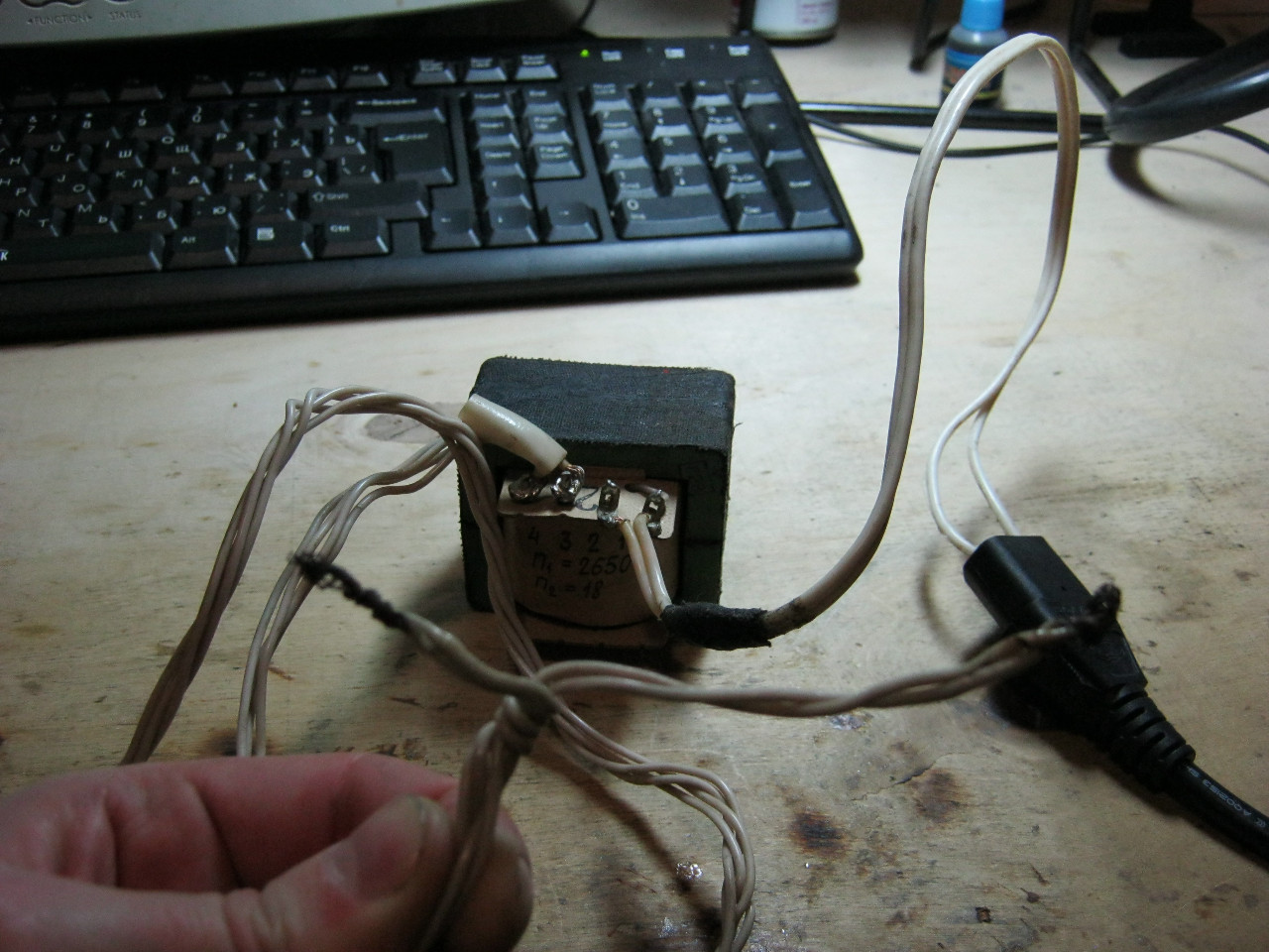
In the photo below, I check the integrity of the primary winding, which consists of 2650 turns. Is there any resistance? So everything is OK. The winding is not broken. If it were open, the multimeter would show “1” on the display.

In the same way, we check the secondary winding, which consists of 18 turns

Transformer operation
Step-down transformer operation
So, our guest is a transformer from a wood burning device:

Its primary winding is the numbers 1, 2.
Secondary winding - numbers 3, 4.
N 1- 2650 turns,
N 2- 18 turns.
![]()
Its insides look like this:
![]()
We connect the primary winding of the transformer to 220 Volts
We put the twist on the multimeter to measure alternating current and measure the voltage on the primary winding (mains voltage).

We measure the voltage on the secondary winding.

It's time to test our formulas
![]()
1.54/224=0.006875 (voltage ratio factor)
18/2650=0.006792 (winding ratio)
We compare the numbers ... the error is generally a penny! The formula works! The error is related to the heating losses of the transformer windings and magnetic circuit, as well as the measurement error of the multimeter. As for the current strength, a simple rule works: By lowering the voltage, we increase the current, and vice versa, by increasing the voltage, we decrease the current.
idle transformer
The operation of the transformer at idle means the operation of the transformer without load on the secondary winding.
Our guinea pig will be another transformer
.JPG)
There are two pairs of secondary windings here, but we will use only one.
The two red wires are the primary winding of the transformer. We will supply voltage from the 220 V network to these wires.
.JPG)
We will remove the voltage from the secondary winding from the two blue wires.
.JPG)
In order to take measurements, we will need to set the knob to measure alternating voltage. If you do not know how to measure alternating voltage and current, I recommend reading this article.
.JPG)
We measure the voltage on the primary winding of the transformer, where we supply 220 V.
.JPG)
The multimeter shows 230 V. Well, it happens).
Now we measure the voltage on the secondary winding of the transformer
.JPG)
Got 22 volts.
I wonder what current strength our transformer consumes from the outlet in idle mode?
.JPG)
The multimeter showed 60 milliamps. It is understandable, because our transformer is not perfect.
As you can see, there is no load on the secondary winding of the transformer, but it still "eats" the current strength, and hence the electrical energy from the network. If we calculate the power, we get P=IU=230×0.06=13.8 watts. And if it stays turned on for at least an hour, then it will consume 13.8 watts * hour or 0.0138 kWh of electricity. And how much does one kilowatt of electricity cost now? In Russia, 4-5 rubles. A penny saves a ruble. Therefore, it is not recommended to leave electrical appliances with a transformer power supply in the network.
Transformer under load
Experience #1
.JPG)
I wonder if the current strength on the primary winding will change if we load the secondary winding with our light bulbs? The bulbs lit up, and the current strength on the primary winding also changed ;-)
.JPG)
When we measured with no load, we had 60 milliamps in the primary circuit. The secondary winding circuit was open for us, since we did not connect any load. As soon as we connected incandescent lamps to the secondary winding of the transformer, they immediately began to consume current. But by the way, the current strength rose in the primary winding circuit, to the level of 65.3 milliamps. This leads to the conclusion:
If the current strength in the secondary winding circuit of the transformer increases, then the current strength in the primary winding circuit also increases.
Experience #2
Let's do one more experiment. To do this, we measure the voltage without load on the secondary winding of the transformer, the so-called idle mode.
.JPG)
and now we connect our light bulbs and measure the voltage again
.JPG)
Wow, the voltage dipped by 0.2 V.
Let's measure the current in the secondary winding with light bulbs
.JPG)
Got 105 milliamps.
All the same similar operations are carried out for a powerful nominal value of 10 ohms and a dissipation power of 10 watts. We measure the voltage on the secondary winding, when the resistor is turned on
.JPG)
We got 18.9 V. Did you see how much the voltage sank? If at idle it was 22.2 V, now it has become 18.9 V!
I wonder how much current flows in the secondary circuit in which the resistor is turned on
.JPG)
Wow, almost 2 amps.
Conclusion: when the load is turned on, a voltage drop occurs. The voltage drops the more, the more current the load eats. Another important factor also plays a role here. transformer power. The greater the power of the transformer, the less the voltage drop will be. The power of the transformer depends on its dimensions. The larger the dimensions, the larger its core size. Therefore, such a transformer can produce a decent amount of current in the secondary winding with minimal voltage drop.
An electrical transformer is a fairly common device used in everyday life for a number of tasks.
And breakdowns can occur in it, which can be identified by a device for measuring electric current parameters - a multimeter.
From this article you will learn how to check the current transformer with a multimeter (ring), and what rules should be followed.
As you know, any transformer consists of the following components:
- primary and secondary coils (there may be several secondary ones);
- core or magnetic circuit;
- frame.
Thus, the list of possible breakdowns is rather limited:
- Damaged core.
- A wire burned out in one of the windings.
- The insulation is broken, as a result of which there is an electrical contact between the turns in the coil (turn-to-turn short circuit) or between the coil and the housing.
- Worn coil leads or contacts.

Current transformer T-0.66 150/5a
Some of the defects are determined visually, so the transformer must first be carefully examined. Here's what you should pay attention to:
- cracks, chips of insulation or its absence;
- condition of bolted connections and terminals;
- swelling of the fill or its leakage;
- blackening on visible surfaces;
- charred paper;
- characteristic smell of burning material.
If there is no obvious damage, the device should be checked for operability using instruments. To do this, you need to know which windings all of its conclusions belong to. On large transducers this information can be represented as a graphic image.
If this is not available, you can use the reference book in which you should find your transformer by marking. If it is part of an electrical appliance, the data source may be a specification or principle circuit diagram.
Methods for testing a transformer with a multimeter
First of all, you should check the condition of the transformer insulation. To do this, the multimeter must be switched to megger mode. After that, measure the resistance:
- between the body and each of the windings;
- between the windings in pairs.
The voltage at which such a test should be carried out is indicated in the technical documentation for the transformer. For example, for most high-voltage models, it is prescribed to measure the insulation resistance at a voltage of 1 kV.

Checking the device with a multimeter
The required resistance value can be found in the technical documentation or in the reference book. For example, for the same high-voltage transformers, it is at least 1 mΩ.
This test is not able to detect turn-to-turn short circuits, as well as changes in the properties of wire and core materials. Therefore, it is imperative to check the performance of the transformer, for which the following methods are used:
 A voltage of 220 volts is not perceived by all devices. lowers the voltage to enable the use of electrical appliances.
How to check a varistor with a multimeter and why you need a varistor, read.
You can familiarize yourself with the rules for checking the voltage in a socket with a multimeter.
Direct method (checking the circuit under load)
It is he who first comes to mind: you need to measure the currents in the primary and secondary windings of a working device, and then, by dividing them by each other, determine the actual transformation ratio. If it corresponds to the passport - the transformer is working, if not - you need to look for a defect. This coefficient can also be calculated independently if the voltage that the device should produce is known.
For example, if 220V / 12V is written on it, then we have a step-down transformer, therefore, the current in the secondary winding should be 220/12 \u003d 18.3 times higher than in the primary (the term "step-down" refers to voltage).

Scheme for verification of a single-phase transformer by direct measurement of primary and secondary voltages using a reference transformer
The load to the secondary winding must be connected in such a way that currents flowing in the windings are not lower than 20% of the nominal values. When turning on, be on your guard: if there is a crackling sound, a burning smell appears, or you see smoke or sparks, the device must be turned off immediately.
If the transformer under test has several secondary windings, then those of them that are not connected to the load must be short-circuited. In an open secondary coil, when the primary is connected to an AC source, high voltage, which can not only disable equipment, but also kill a person.

Serial connection of transformer windings using a battery and a multimeter
If we are talking about a high-voltage transformer, then before turning it on, you need to check whether its core needs to be grounded. This is evidenced by the presence of a special terminal marked with the letter "Z" or a special icon.
The direct method of checking the transformer allows you to fully assess the state of the latter. However, it is far from always possible to turn on the transformer with a load and make all the necessary measurements.
If, due to safety or other reasons, this cannot be done, the condition of the device is checked indirectly.
indirect method
Part this method includes several tests, each of which displays the state of the device in one aspect. Therefore, it is desirable to carry out all these tests in combination.
Determination of the reliability of the marking of the winding leads
To perform this test, the multimeter must be switched to ohmmeter mode. Next, you need to “ring” all the available conclusions in pairs. Between those that belong to different coils, the resistance will be equal to infinity. If the multimeter shows a specific value, then the conclusions belong to the same coil.
Here you can compare the measured resistance with that given in the reference book. If there is a discrepancy of more than 50%, then an interturn short circuit or partial destruction of the wire has occurred.
![]()
Connecting a transformer to a multimeter
Please note that on coils with a large inductance, that is, consisting of a significant number of turns, the digital multimeter may erroneously show an overestimated resistance. In such cases, it is advisable to use an analog device.
The windings should be checked with direct current, which the transformer cannot convert. When using an alternating current, an EMF will be induced in other coils and it is quite possible that it will be quite high. So, if an alternating voltage of only 20 V is applied to the secondary coil of a 220/12 V step-down transformer, then a voltage of 367 V will appear at the primary terminals and, if accidentally touched, the user will receive a strong electric shock.
Next, you need to determine which pins should be connected to the current source, and which to the load. If it is known that the transformer is step-down, then the coil with the largest number of turns and the greatest resistance should be connected to the current source. With a step-up transformer, the opposite is true.

All methods of measuring the strength of electric current
But there are models that have both step-down and step-up coils among the secondary coils. Then the primary coil can be recognized with a certain degree of probability by the following features: its conclusions are usually mounted away from the others, and the coil can also be located on the frame in a separate section.
The development of the Internet has made this method possible: you need to take a picture of the transformer and write a request with the attached photo and all the available information (brand, etc.) to one of the network thematic forums.
Perhaps one of its participants has dealt with such devices and can tell in detail how to connect it.
If there are intermediate taps in the secondary coil, its beginning and end must be recognized. To do this, you need to determine the polarity of the outputs.
Determining the polarity of the winding leads
In the role of a meter, you should use a magnetoelectric ammeter or voltmeter, in which the polarity of the leads is known. The device must be connected to the secondary coil. It is most convenient to use those models in which "zero" is located in the middle of the scale, but in the absence of such, the classic one is also suitable - with the location of "zero" on the left.
If there are several secondary coils, the others must be shunted.

Checking the polarity of the phase windings of electrical AC machines
Pass through the primary coil D.C. little strength. As a source the usual one will do battery, while a resistor must be included in the circuit between it and the coil - so that a short circuit does not occur. An incandescent lamp can serve as such a resistor.
It is not necessary to install a switch in the circuit of the primary coil: it is enough to follow the arrow of the multimeter to close the circuit, touching the wire from the coil output lamp, and immediately open it.
If the same poles from the battery and the multimeter are connected to the terminals of the coils, that is, the polarity is the same, then the arrow on the device will twitch to the right.
With bipolar connection - to the left.
At the moment of power off, the opposite picture will be observed: with a unipolar connection, the arrow will move to the left, with a bipolar connection - to the right.
On a device with a “zero” at the beginning of the scale, the movement of the arrow to the left is more difficult to notice, since it almost immediately bounces off the limiter. Therefore, you need to watch carefully.
In the same way, the polarities of all other coils are checked.
 A multimeter is a very necessary device for measuring current strength, which is used to troubleshoot certain devices. – read helpful tips optionally.
Instructions for checking diodes with a multimeter are presented.
Removing the magnetization characteristic
To be able to use this method, you need to prepare ahead of time: while the transformer is new and known to be in good condition, its so-called current-voltage characteristic (CVC) is taken. This is a graph showing the dependence of the voltage at the terminals of the secondary coils on the magnitude of the magnetization current flowing in them.

Schemes of removal of characteristics of magnetization
Having opened the circuit of the primary coil (so that the results are not distorted by interference from nearby power equipment), an alternating current of various strengths is passed through the secondary, each time measuring the voltage at its input.
The power used for this power supply must be sufficient to saturate the magnetic circuit, which is accompanied by a decrease in the slope of the saturation curve to zero (horizontal position).
Measuring instruments must refer to an electrodynamic or electromagnetic system.
Before and after the test, the magnetic circuit must be demagnetized by increasing the current strength in the winding in several approaches, followed by its decrease to zero.
As the device is used, it is necessary to take the current-voltage characteristic with a certain frequency and compare it with the original one. A decrease in its steepness will indicate the appearance of an interturn short circuit.
Related video


