How to determine the windings of a transformer by resistance. What is the primary winding of a transformer? Rod transformers, features
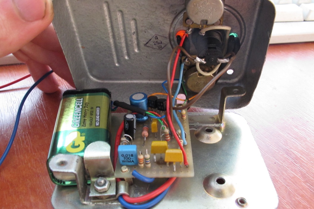
Hello. I will go over a hackneyed topic today, so the article will be useful to those who have not yet learned how to determine the parameters of an unknown transformer. I have long wanted to write an article about this, but there was no more or less decent transformer. Today I removed the transformer from the microwave of the times of the USSR, I will determine what voltages are on it and show you.
Well, let's start with the fact that it is generally accepted to ring the windings for resistance and where the resistance is greater than that network. This method has the right to life, but not for all transformers. Anode filament is hard to determine where the network is, just as hard to determine if there are two symmetrical windings of 110V or 127V. How to deal with a transformer like my hero of the article in the photo, which has 14 inputs
At the time of this writing, I will forget where I removed the transformer from, I will forget where everything was included. I’ll take a multimeter in ohmmeter mode at the limit of 200 ohms and start measuring and immediately recording which windings are connected and what resistance they have. For convenience, I will mark the windings on paper.

As a result, I have a table of resistances (did not take into account the resistance of the multimeter probes, so the readings are not accurate) and a transformer circuit. It’s already clear from the diagram that the network is a winding between contacts 1-2, but how to determine if there were still windings with high resistance, say 20 Ohm or 30 Ohm.
Everything is simple here, the network winding is usually wound first. But it's worth it to be safe. I take a 220V 40W light bulb and turn it on in series with the windings, as described in the article. You need to start with the winding with the highest resistance, and move towards decreasing resistance. If the lamp begins to specifically highlight, then the XX current has begun to exceed the norm.
I select the previous winding and now connect the transformer through a fuse. I leave it for an hour and see how it heats up. If the trance is slightly warm, then the winding is selected correctly. On this winding, the transformer should produce the rated rated power, in my case it should pull 180-200W
And finally, it remains to measure the voltage on the remaining windings. Winding 13-14 is a tap on the other side wound with a thick wire of at least 2.5 squares. The remaining windings are wound with 0.51mm kv wire, which means that each winding will withstand about 1A  The voltages for my tasks are not quite standard, but maybe it will come in handy somewhere without rewinding
That's all for now. Hope it was helpful and interesting. If you like my articles, I recommend subscribing to updates contact or Odnoklassniki not to miss something new
With uv. Edward
The primary winding of the transformer is the part of the device to which the converted alternating current is supplied. Determine which is primary and which secondary winding transformer, important when using devices without factory markings and homemade coils.
There are no primary winding designations on homemade transformers.
Knowledge of the internal structure and principle of operation of transformers is of practical importance for beginner radio amateurs and home craftsmen. Having information about the types of windings, methods for calculating them and the main differences, you can start creating lighting systems and other devices with more confidence.
Types of transformer windings
Depending on the relative position of the current-conducting elements, the direction of their winding and the cross-sectional shape of the wire, several types of transformer windings are distinguished:
- Single-layer or double-layer cylindrical winding made of rectangular wire. The technology of its manufacture is very simple, due to which such coils are widely used. The winding has a small thickness, which reduces the heating of the device. Of the shortcomings, a small strength of the structure should be highlighted.
- The multilayer cylindrical winding is similar to the previous type, but the wire is arranged in several layers. In this case, the windows of the magnetic system are filled better, but there is a problem of overheating.
- A cylindrical multilayer winding made of round wire has properties similar to the previous types of windings, but the loss of strength is added to the disadvantages as power increases.
- The screw winding with one, two or more turns has high strength, excellent insulation and cooling. Compared to cylindrical windings, helical windings are more expensive to manufacture.
- A continuous winding of rectangular wire does not overheat, it has a significant margin of safety.
- The multilayer foil winding is resistant to damage and fills the window of the magnetic system well, but the production technology of such coils is complex and expensive.
![]()
Transformers have six basic winding types.
On the diagrams of transformers, the beginning of the high voltage windings is indicated by capital letters of the Latin alphabet (A, B, C), and the same part of the low voltage wires is indicated by lowercase letters. The opposite end of the winding has a generally accepted symbol, consisting of the final three letters of the Latin alphabet - X, Y, Z for the input voltage and x, y, z for the output.
Windings are distinguished by purpose:
- the main ones - these include the primary and secondary windings, through which the current is supplied from the network and flows to the place of consumption;
- regulating - are branches, main function which is the change in the voltage transformation ratio;
- auxiliary - are used to meet the needs of the transformer itself.
Automated calculation of transformer winding
Choosing the right transformer is important not only when carrying out repairs electrical network, lighting systems and control circuits. The calculation is also important for radio amateurs who want to independently manufacture a coil for the device being designed.
For this, there are convenient calculator programs that have wide functionality and operate with various calculation methods.
![]()
Special programs will facilitate the calculation of the transformer.
- voltage supplied to the primary winding of the coil, in most cases this is for domestic use
- voltage is 220 volts;
- voltage on the secondary winding;
- current strength of the secondary winding.
The result of the calculations is presented in the form of a convenient table, which indicates such values as the parameters of the core and the height of the rod, the wire cross section, the number of turns and the power of the windings.
Automated calculation greatly simplifies the theoretical part of the transformer design process, allowing you to focus on the important details.
Differences between the primary winding and the secondary

You can determine the type of winding by its resistance.
Determining the type of winding can be important in cases where no designations have been preserved on the transformer. How to find out where is the primary and where is the secondary winding? They are rated for different voltages. If a secondary winding is connected to a 220 V network, the device will simply burn out.
The main visual criterion by which you can determine the type of winding is the thickness of the wire soldered to its conclusions. The transformer has 4 outputs: two for connecting to the network, and two more for voltage output. The wires with which the primary winding is connected to the network are of small thickness. The secondary winding is connected by wires of a rather large cross section.
Another sure sign that allows you to find out the type of winding is measuring the resistance of the wire. The resistance of the primary winding has a rather high value when it can be up to 1 Ohm for the secondary.
Regardless of the model, the primary winding of the transformer will always be the same. On the circuit diagrams it is denoted by the Roman numeral I. There can be several secondary windings, their designation is II, III, IV, etc. You should not make a common mistake by calling such windings tertiary, quaternary, and so on. All of them have the same rank and are called secondary.
What is the function of a transformer?

Transformers are widely used in chargers Oh.
The main function of transformers is to decrease or increase the voltage of the current supplied to them. These devices are widely used in high-voltage networks that deliver electricity from the place of its generation to the final consumer.
In a modern household, it is difficult to do without a current transformer. These devices are used in all types of equipment, from refrigerators to computers.
More recently, dimensions and weight household appliances often determined precisely by the parameters of the transformer, because the basic rule was that the higher the power of the current converter, the larger and heavier it is. To see this, it is enough just to compare the two types of chargers. Transformers from the old mobile phone and a modern smartphone or tablet. In the first case, we will have a small but weighty charging device, which heats up noticeably and often fails. Pulse transformers are characterized by silent operation, compactness and high reliability. The principle of their operation is that the alternating voltage is first supplied to the rectifier and converted into high-frequency pulses that are fed to a small transformer.
In the conditions of repairing equipment at home, there is often a need for self-winding of the transformer coil. For this, prefabricated cores are used, which consist of individual plates. The parts are interconnected by means of a lock, forming a rigid structure. Wire winding is carried out using a home-made device that works on the principle of a rotation.
When creating such a transformer, it should be remembered: the denser and more accurately the wire is wound, the fewer problems will arise with the operation of such a device.
The turns are separated from each other by a single layer of paper smeared with glue, and the primary winding is separated from the secondary by an interval of 4-5 layers of paper. Such isolation will provide protection against breakdowns and short circuits. A properly assembled transformer guarantees the stability of the equipment, the absence of annoying hum and overheating.
Conclusion on the topic
Transformers are used in most of the technology around us. Knowledge of their internal structure makes it possible, if necessary, to repair, service or replace them.
It is important to distinguish the primary winding from the secondary winding for correct connection devices to the network. A similar problem can occur when using homemade devices or unmarked transformers.
Continuous coil winding is used only at voltages of 110 kV and above. When using several parallel wires in a winding, the transposition is done as in helical parallel windings.
AT modern technology transformers are used quite often. These devices are used to increase or decrease the parameters of a variable electric current. The transformer consists of input and several (or at least one) output windings on a magnetic core. These are its main components. It happens that the device fails and it becomes necessary to repair or replace it. To determine whether the transformer is working, you can use a home multimeter on your own. So, how to check the transformer with a multimeter?
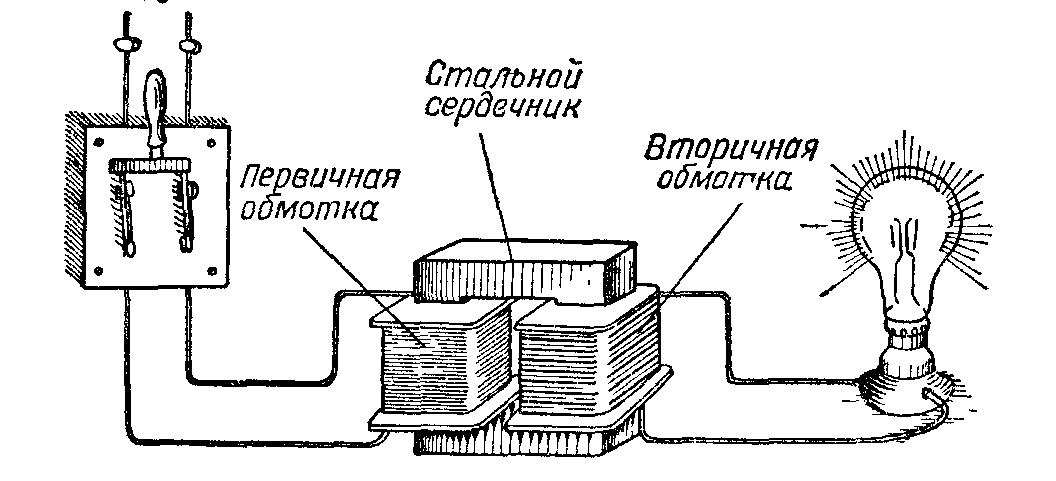
Fundamentals and principle of operation
The transformer itself belongs to the elementary devices, and the principle of its operation is based on the two-way transformation of the excited magnetic field. Tellingly, a magnetic field can only be induced using alternating current. If you have to work with a constant, you must first convert it.
A primary winding is wound on the core of the device, to which an external alternating voltage with certain characteristics is supplied. It is followed by it or several secondary windings, in which an alternating voltage is induced. The transmission coefficient depends on the difference in the number of turns and the properties of the core.
Varieties
There are many types of transformers on the market today. Depending on the design chosen by the manufacturer, a variety of materials can be used. As for the shape, it is chosen solely from the convenience of placing the device in the appliance case. The design power is only affected by the configuration and material of the core. At the same time, the direction of the turns does not affect anything - the windings are wound both towards and away from each other. The only exception is the identical choice of direction if multiple secondary windings are used.

To test such a device, a conventional multimeter is sufficient, which will be used as a current transformer tester. No special devices are required.
Checking procedure
The transformer test begins with the definition of the windings. This can be done by marking on the device. The pin numbers should be indicated, as well as their type designations, which allows you to establish more information from the directories. In some cases, there are even explanatory drawings. If the transformer is installed in some electronic device, then the fundamental electronic circuit this device, as well as detailed specifications.

So, when all the conclusions are determined, the tester's turn comes. With it, you can install the two most common malfunctions - a short circuit (to the case or an adjacent winding) and a winding break. In the latter case, in the ohmmeter mode (resistance measurement), all windings call back in turn. If any of the measurements shows one, that is, infinite resistance, then there is a break.
There is an important nuance here. It is better to check on an analog device, since a digital one can give distorted readings due to high induction, which is especially true for windings with a large number turns.
When a short circuit to the case is being checked, one of the probes is connected to the winding terminal, while the second leads to the conclusions of all other windings and the case itself. To check the latter, you will first need to clean the place of contact from varnish and paint.
Interturn Fault Definition
Another common transformer failure is interturn short circuit. It is almost impossible to check a pulse transformer for such a malfunction with only a multimeter. However, if you involve the sense of smell, attentiveness and sharp vision, the problem may well be solved.
A bit of theory. The wire on the transformer is insulated exclusively with its own varnish coating. If there is an insulation breakdown, the resistance between adjacent turns remains, as a result of which the contact point heats up. That is why the first step is to carefully inspect the device for the appearance of streaks, blackening, burnt paper, swelling and burning smell.
Next, we try to determine the type of transformer. As soon as this is obtained, according to specialized reference books, you can see the resistance of its windings. Next, we switch the tester to the megohmmeter mode and begin to measure the insulation resistance of the windings. In this case, the tester pulse transformers It's just a regular multimeter.
Each measurement should be compared with that specified in the handbook. If there is a discrepancy of more than 50%, then the winding is faulty.
If the resistance of the windings is not indicated for one reason or another, other data must be given in the reference book: the type and cross section of the wire, as well as the number of turns. With their help, you can calculate the desired indicator yourself.
Checking household step-down devices
It should be noted the moment of checking classic step-down transformers with a tester-multimeter. You can find them in almost all power supplies that lower the input voltage from 220 volts to the output voltage of 5-30 volts.
The first step is to check the primary winding, which is supplied with a voltage of 220 volts. Signs of a primary winding failure:
- the slightest visibility of smoke;
- the smell of burning;
- crack.
In this case, you should immediately stop the experiment.
If everything is fine, you can proceed to the measurement on the secondary windings. You can only touch them with the contacts of the tester (probes). If the results obtained are less than the control ones by at least 20%, then the winding is faulty.
Unfortunately, it is possible to test such a current block only in cases where there is a completely similar and guaranteed working block, since it is from it that the control data will be collected. It should also be remembered that when working with indicators of the order of 10 ohms, some testers may distort the results.
No-load current measurement
If all tests have shown that the transformer is fully functional, it will not be superfluous to conduct another diagnosis - for the current of the idle transformer. Most often, it is equal to 0.1-0.15 of the nominal value, that is, the current under load.

For verification measuring device switch to ammeter mode. Important point! The multimeter should be connected short-circuited to the transformer under test.
This is important because during the supply of electricity to the transformer winding, the current strength increases up to several hundred times in comparison with the nominal one. After that, the tester probes open, and the indicators are displayed on the screen. It is they who display the value of the current without load, the no-load current. In a similar way, the indicators are measured on the secondary windings.
To measure the voltage, a rheostat is most often connected to the transformer. If it is not at hand, a tungsten spiral or a row of light bulbs can be used.
To increase the load, increase the number of light bulbs or reduce the number of turns of the spiral.
As you can see, no special tester is even required for verification. A normal multimeter will do. It is highly desirable to have at least an approximate understanding of the principles of operation and the design of transformers, but for a successful measurement, it is enough just to be able to switch the device to ohmmeter mode.
An electrical transformer is a fairly common device used in everyday life for a number of tasks.
And breakdowns can occur in it, which can be identified by a device for measuring electric current parameters - a multimeter.
From this article you will learn how to check the current transformer with a multimeter (ring), and what rules should be followed.
As you know, any transformer consists of the following components:
- primary and secondary coils (there may be several secondary ones);
- core or magnetic circuit;
- frame.
Thus, the list of possible breakdowns is rather limited:
- Damaged core.
- A wire burned out in one of the windings.
- The insulation is broken, as a result of which there is an electrical contact between the turns in the coil (turn-to-turn short circuit) or between the coil and the housing.
- Worn coil leads or contacts.

Current transformer T-0.66 150/5a
Some of the defects are determined visually, so the transformer must first be carefully examined. Here's what you should pay attention to:
- cracks, chips of insulation or its absence;
- condition of bolted connections and terminals;
- swelling of the fill or its leakage;
- blackening on visible surfaces;
- charred paper;
- characteristic smell of burning material.
If there is no obvious damage, the device should be checked for operability using instruments. To do this, you need to know which windings all of its conclusions belong to. On large transducers this information can be represented as a graphic image.
If this is not available, you can use the reference book in which you should find your transformer by marking. If it is part of an electrical appliance, the data source may be a specification or a circuit diagram.
Methods for testing a transformer with a multimeter
First of all, you should check the condition of the transformer insulation. To do this, the multimeter must be switched to megger mode. After that, measure the resistance:
- between the body and each of the windings;
- between the windings in pairs.
The voltage at which such a test should be carried out is indicated in the technical documentation for the transformer. For example, for most high-voltage models, it is prescribed to measure the insulation resistance at a voltage of 1 kV.

Checking the device with a multimeter
The required resistance value can be found in the technical documentation or in the reference book. For example, for the same high-voltage transformers, it is at least 1 mΩ.
This test is not able to detect turn-to-turn short circuits, as well as changes in the properties of wire and core materials. Therefore, it is imperative to check the performance of the transformer, for which the following methods are used:
 A voltage of 220 volts is not perceived by all devices. lowers the voltage to enable the use of electrical appliances.
How to check a varistor with a multimeter and why you need a varistor, read.
You can familiarize yourself with the rules for checking the voltage in a socket with a multimeter.
Direct method (checking the circuit under load)
It is he who first comes to mind: you need to measure the currents in the primary and secondary windings of a working device, and then, by dividing them by each other, determine the actual transformation ratio. If it corresponds to the passport - the transformer is working, if not - you need to look for a defect. This coefficient can also be calculated independently if the voltage that the device should produce is known.
For example, if 220V / 12V is written on it, then we have a step-down transformer, therefore, the current in the secondary winding should be 220/12 \u003d 18.3 times higher than in the primary (the term "step-down" refers to voltage).

Scheme for verification of a single-phase transformer by direct measurement of primary and secondary voltages using a reference transformer
The load to the secondary winding must be connected in such a way that currents flowing in the windings are not lower than 20% of the nominal values. When turning on, be on your guard: if there is a crackling sound, a burning smell appears, or you see smoke or sparks, the device must be turned off immediately.
If the transformer under test has several secondary windings, then those of them that are not connected to the load must be short-circuited. In an open secondary coil, when the primary is connected to an AC source, high voltage, which can not only disable equipment, but also kill a person.

Serial connection of transformer windings using a battery and a multimeter
If we are talking about a high-voltage transformer, then before turning it on, you need to check whether its core needs to be grounded. This is evidenced by the presence of a special terminal marked with the letter "Z" or a special icon.
The direct method of checking the transformer allows you to fully assess the state of the latter. However, it is far from always possible to turn on the transformer with a load and make all the necessary measurements.
If, due to safety or other reasons, this cannot be done, the condition of the device is checked indirectly.
indirect method
Part this method includes several tests, each of which displays the state of the device in one aspect. Therefore, it is desirable to carry out all these tests in combination.
Determination of the reliability of the marking of the winding leads
To perform this test, the multimeter must be switched to ohmmeter mode. Next, you need to “ring” all the available conclusions in pairs. Between those that belong to different coils, the resistance will be equal to infinity. If the multimeter shows a specific value, then the conclusions belong to the same coil.
Here you can compare the measured resistance with that given in the reference book. If there is a discrepancy of more than 50%, then an interturn short circuit or partial destruction of the wire has occurred.
![]()
Connecting a transformer to a multimeter
Please note that on coils with a large inductance, that is, consisting of a significant number of turns, the digital multimeter may erroneously show an overestimated resistance. In such cases, it is advisable to use an analog device.
The windings should be checked with direct current, which the transformer cannot convert. When using an alternating current, an EMF will be induced in other coils and it is quite possible that it will be quite high. So, if an alternating voltage of only 20 V is applied to the secondary coil of a 220/12 V step-down transformer, then a voltage of 367 V will appear at the primary terminals and, if accidentally touched, the user will receive a strong electric shock.
Next, you need to determine which pins should be connected to the current source, and which to the load. If it is known that the transformer is step-down, then the coil with the largest number of turns and the greatest resistance should be connected to the current source. With a step-up transformer, the opposite is true.

All methods of measuring the strength of electric current
But there are models that have both step-down and step-up coils among the secondary coils. Then the primary coil can be recognized with a certain degree of probability by the following features: its conclusions are usually mounted away from the others, and the coil can also be located on the frame in a separate section.
The development of the Internet has made this method possible: you need to take a picture of the transformer and write a request with the attached photo and all the available information (brand, etc.) to one of the network thematic forums.
Perhaps one of its participants has dealt with such devices and can tell in detail how to connect it.
If there are intermediate taps in the secondary coil, its beginning and end must be recognized. To do this, you need to determine the polarity of the outputs.
Determining the polarity of the winding leads
In the role of a meter, you should use a magnetoelectric ammeter or voltmeter, in which the polarity of the leads is known. The device must be connected to the secondary coil. It is most convenient to use those models in which "zero" is located in the middle of the scale, but in the absence of such, the classic one is also suitable - with the location of "zero" on the left.
If there are several secondary coils, the others must be shunted.

Checking the polarity of the phase windings of electrical AC machines
Pass through the primary coil D.C. little strength. As a source the usual one will do battery, while a resistor must be included in the circuit between it and the coil - so that a short circuit does not occur. An incandescent lamp can serve as such a resistor.
It is not necessary to install a switch in the circuit of the primary coil: it is enough to follow the arrow of the multimeter to close the circuit, touching the wire from the coil output lamp, and immediately open it.
If the same poles from the battery and the multimeter are connected to the terminals of the coils, that is, the polarity is the same, then the arrow on the device will twitch to the right.
With bipolar connection - to the left.
At the moment of power off, the opposite picture will be observed: with a unipolar connection, the arrow will move to the left, with a bipolar connection - to the right.
On a device with a “zero” at the beginning of the scale, the movement of the arrow to the left is more difficult to notice, since it almost immediately bounces off the limiter. Therefore, you need to watch carefully.
In the same way, the polarities of all other coils are checked.
 A multimeter is a very necessary device for measuring current strength, which is used to troubleshoot certain devices. – read helpful tips optionally.
Instructions for checking diodes with a multimeter are presented.
Removing the magnetization characteristic
To be able to use this method, you need to prepare ahead of time: while the transformer is new and known to be in good condition, its so-called current-voltage characteristic (CVC) is taken. This is a graph showing the dependence of the voltage at the terminals of the secondary coils on the magnitude of the magnetization current flowing in them.

Schemes of removal of characteristics of magnetization
Having opened the circuit of the primary coil (so that the results are not distorted by interference from nearby power equipment), an alternating current of various strengths is passed through the secondary, each time measuring the voltage at its input.
The power used for this power supply must be sufficient to saturate the magnetic circuit, which is accompanied by a decrease in the slope of the saturation curve to zero (horizontal position).
Measuring instruments must refer to an electrodynamic or electromagnetic system.
Before and after the test, the magnetic circuit must be demagnetized by increasing the current strength in the winding in several approaches, followed by its decrease to zero.
As the device is used, it is necessary to take the current-voltage characteristic with a certain frequency and compare it with the original one. A decrease in its steepness will indicate the appearance of an interturn short circuit.
Related video
The first thing to do is take a piece of paper, a pencil and a multimeter. Using all this, ring the transformer windings and draw a diagram on paper. You should end up with something very similar to Figure 1.
The conclusions of the windings in the picture should be numbered. It is possible that there will be much fewer outputs, in the simplest case there are only four: two outputs of the primary (network) winding and two outputs of the secondary. But this does not always happen, more often there are several more windings.
Some conclusions, although they exist, may not “ring” with anything. Are these windings broken? Not at all, most likely these are shielding windings located between other windings. These ends are usually connected to a common wire - the "ground" of the circuit.
Therefore, it is desirable to write down the winding resistances on the resulting circuit, since main goal research is to determine the network winding. Its resistance, as a rule, is greater than that of other windings, tens and hundreds of ohms. Moreover, the smaller the transformer, the greater the resistance of the primary winding: the small diameter of the wire affects and a large number of turns. The resistance of the lowering secondary windings is almost zero - a small number of turns and a thick wire.

Rice. 1. Transformer winding diagram (example)
Suppose that the winding with the highest resistance was found, and we can consider it network. But you don't need to turn it on right away. To avoid explosions and other unpleasant consequences, it is best to test it by turning on in series with the winding a 220V light bulb with a power of 60 ... 100 W, which will limit the current through the winding at 0.27 ... 0.45A.
The power of the light bulb should approximately correspond to the overall power of the transformer. If the winding is determined correctly, then the light does not light, in extreme cases, the filament is slightly warm. In this case, you can almost safely turn on the winding in the network, for starters, it is better to use a fuse for a current of no more than 1 ... 2A.
If the light bulb burns brightly enough, then it may turn out to be a 110 ... 127V winding. In this case, you should ring the transformer again and find the second half of the winding. After that, connect the halves of the windings in series and re-enable. If the light goes out, then the windings are connected correctly. AT otherwise swap the ends of one of the found half-windings.
So, we will assume that the primary winding was found, the transformer was connected to the network. The next thing to do is to measure the no-load current of the primary winding. For a serviceable transformer, it is no more than 10 ... 15% of the rated current under load. So for a transformer, the data of which is shown in Figure 2, when powered from a 220V network, the no-load current should be in the range of 0.07 ... 0.1A, i.e. no more than one hundred milliamps.

Rice. 2. Transformer CCI-281
How to measure the no-load current of a transformer
The no-load current should be measured with an AC ammeter. At the same time, at the moment of connection to the network, the ammeter terminals must be short-circuited, since the current when the transformer is turned on can be a hundred or more times higher than the nominal one. Otherwise, the ammeter may simply burn out. Next, we open the terminals of the ammeter and look at the result. During this test, let the transformer run for 15 ... 30 minutes, and make sure that there is no noticeable heating of the winding.
The next step is to measure the voltage on the secondary windings without load, - no-load voltage. Let's assume that the transformer has two secondary windings, and the voltage of each of them is 24V. Almost what is needed for the amplifier discussed above. Next, we check the load capacity of each winding.
To do this, it is necessary to connect a load to each winding, ideally a laboratory rheostat, and by changing its resistance to ensure that the voltage across the winding drops by 10-15%. This can be considered the optimal load for this winding.
Along with the voltage measurement, the current is also measured. If the indicated voltage drop occurs at a current, for example 1A, then this is the rated current for the winding under test. Measurements should be started by setting the R1 rheostat slider to the right position according to the diagram.
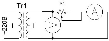
Figure 3. Scheme of testing the secondary winding of the transformer
Instead of a rheostat, you can use light bulbs or a piece of a spiral from an electric stove as a load. Measurements should begin with a long piece of spiral or with the connection of one light bulb. To increase the load, you can gradually shorten the spiral, touching it with a wire at different points, or increasing the number of connected lamps one at a time.
To power the amplifier, one winding with a midpoint is required (see article). We connect two secondary windings in series and measure the voltage. It should be 48V, the connection point of the windings will be the middle point. If, as a result of the measurement, the voltage at the ends of the windings connected in series is zero, then the ends of one of the windings should be swapped.
In this example, everything turned out almost successfully. But more often it happens that the transformer has to be rewound, leaving only the primary winding, which is already almost half the battle. How to calculate a transformer is a topic for another article, here it was only about how to determine the parameters of an unknown transformer.