How to make a lamp from an LED strip with your own hands. Converting a fluorescent lamp to LED Converting a fluorescent table lamp
Converting a failed fluorescent lamp into an LED lamp is a very good idea. Diodes with comparable power consumption shine brighter and last longer. The method of converting a fluorescent lamp into an LED lamp depends on the type of lamp itself.
Types of luminaire designs for fluorescent lamps:
- linear;
- compact.
How to convert a linear fluorescent light into an LED one
If you have a lamp with a linear body, converting it into an LED version is not difficult. The easiest way is to use diode strips. There are even options for connecting to a 220V network without special power drivers. Their peculiarity is that all LEDs are connected in series and the output of one of them will render the entire segment inoperable.
The connection diagram is very simple:
Characteristics LED strip at 220V:
- Matrix type: SMD 5050;
- number of diodes per linear meter: 60 pcs. (60 x 3.5V = 210V);
- load power: 10W;
- light flow: 2100Lm.
In terms of brightness, a meter of such tape will correspond to an ordinary 100W incandescent light bulb.
Design advantages:
- Very simple and quick installation and connection.
Design flaws:
- Due to the lack of a smoothing capacitor, the LEDs flicker at a frequency of 100 Hz. According to sanitary standards, such lighting sources cannot be used in residential premises.
- Along the entire length of the tape a large number of contact pads through which 220V voltage passes. To prevent short circuits, this type of tape is only available in sealed housing, which makes it difficult to repair if one of the diode matrices burns out.
- The minimum segment length of 50cm makes it difficult to create compact structures.
The main disadvantage of such tapes is high-frequency flicker. It is practically not perceived by vision, but causes rapid fatigue when performing precise work or reading. The problem is partially solved by installing a high-voltage capacitor in front of the diode bridge at the rate of 60-70 μF x 500V per 10W of tape power.

How to convert a fluorescent table lamp to LED
Remake such a lamp little blood, mounting a 220V tape there will not work. With a minimum segment length of 50cm, it will not fit into the body, and its design has a very negative attitude towards bends. Several strips can be installed in such a lamp diode strips designed for voltage 12V.
The optimal design option in this case is:

We use four 25 cm strips with 12V wiring. As a result, the brightness will be at the level of 75W of an incandescent lamp.
Power supply for compact lamp
A meter of tape consumes about 15W and is designed for a current of 1.2A. For such power, it makes no sense to buy a 30-watt specialized driver. You can use a ready-made factory solution. This miniature power supply with a total power of up to 20W. But the dimensions of 79 x 30 x 24 mm will not allow it to fit into the lamp body.

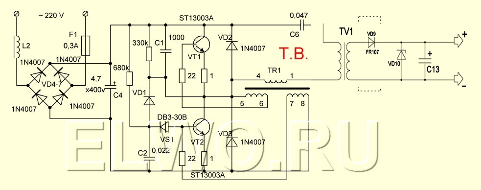
You can assemble a compact switching power supply with your own hands according to the following scheme. Capacitor 20-30 uF x 400V, zener diode 9-12V.

How to convert base fluorescent lamps into LED lamps
There are two options for modifying such a light bulb into an LED one:
- use of diode strip segments;
- Compact lamp with bright LEDs.
Conversion for LED strip
Materials for conversion and connection diagram:

Detailed video instructions for the modification:
 For compact tabletop solutions, you can convert a fluorescent lamp to an LED lamp as follows. Unlike the previous option, this design provides a directional luminous flux and is ideal for illuminating the workplace. Diodes can be used at 0.5 or 1 W. Then the final brightness will be 350Lm or 700Lm, respectively.
To power the structure, you can use any 12V 2A power supply if you connect all the LEDs in parallel, or charger from mobile phone at 5V 2A when connected in three parallel lines.
Power drivers for energy-saving light bulbs are not suitable for LEDs, so we can safely unsolder the wires going to the base from them, and send the boards themselves for further processing.
Fluorescent lamps are much more economical than incandescent lamps; for the same power, their luminous output is several times greater. The service life of fluorescent lamps is written to be 5 years, provided that the number of switches on does not exceed more than 5 times a day. But, in practice, they nurse for much less than 1-1.5, maximum 2 years.
In this article we will look at specific model table fluorescent lamp - Delux - TF-01.
The design of the lamp itself is excellent: it is attached to the table edge and does not take up space on the table, good design, it has an oblong lampshade, which allows you to conveniently adjust the lighting on a computer desk without illuminating the monitor, for example, but only illuminating the keyboard. Economical, lamp power 11 W. But this lamp has one very significant drawback - the lamps themselves do not burn for a long time, a maximum of six months. When they were not yet so expensive (before the crisis in Ukraine), it was tolerable, but when the price increased several times, the advisability of using such a table lamp simply disappeared.
And so the idea arose to convert it to LED. In principle, this is not so difficult to do; LED panels are now sold in any Radio Components store. But in order to feed them, you need constant pressure 12 V, which means you need to make a 12 volt power supply.

There are 2 options for manufacturing such a power supply: limit the current with a high-voltage capacitor (400-600 V) to 200-300 mA, then convert the alternating voltage to direct voltage - rectify it, and then limit and stabilize it at 12 V. The dimensions of the power supply in this situation are minimal and it would fit in the lampshade housing. Using this scheme, industrial LED lamps are made, which look like a regular incandescent light bulb and are screwed into a standard socket. But the big disadvantage of this scheme is that if some radio component of the power supply fails, the LEDs (sockets) instantly break through and also fail (burn out), and they are expensive.
Therefore, it was decided to make a power supply using a step-down transformer according classic scheme. And by the way, in this case you can easily adjust the output voltage. This is important so that the LEDs operate in nominal mode and do not overheat, then they will last a very long time, 5, 10 years, or more.
When remaking the desk fluorescent lamp - Delux - TF-01, 4 LED panels were used, each with a power of 0.3 W, i.e. The total result is a 1.2 W LED lamp. At the same time, the light is excellent, lights up instantly, and shines almost for free :)) We throw away all the old electronics from the lamp, or rather, we disassemble it for spare parts.
I selected a 2 W transformer, a bridge, a 12 V bank (K142EN8B or KR142EN8B, or an imported analogue of a 12 V voltage stabilizer - 7812) and a pair of capacitors. True, I had to tinker a little to assemble the LED panels into a block and secure the homemade LED lamp in the lampshade. I cut off a strip of fiberglass and secured the panels to it with self-tapping screws, and then attached this strip with panels to plastic stands, which I glued to the lampshade body with dichloroethane glue. Krenka, as you can see, was placed on a small radiator for reliability. If any surges appear in the network, banks and capacitors smooth out everything.
In terms of money, such a lamp would not cost more than buying an original fluorescent lamp, but it would last tens of times longer.
Well, just like that, you can tinker with the rework once and not go to the store for new lamps for 5-7 years, or even longer, and at the same time reduce electricity consumption by 10 times, compared to fluorescent lamps, and by 60 or 75 times - compared to an incandescent lamp. The benefits are clear...
I've been using this lamp for 2 years now and I'm very pleased.
The modern small-sized table lamp, which is shown in the photograph, with a light source installed in it in the form of a fluorescent U-shaped compact lamp, worked for several years and failed.
According to the owner table lamp, recently, when the lamp was still working, there was an unpleasant smell coming from its base.

Opening the base of the lamp immediately showed what the problem was. The insulation in one of the windings of the ballast device was burnt. Apparently from overheating or Bad quality insulation of the winding wire of the coil, a short circuit occurred between the turns, which provoked the heating of the winding to a high temperature and the final failure of the ballast device.
I didn’t want to bother with rewinding the coils, and it was almost impossible to find a ready-made ballast device for replacement, especially since its type was unknown. Therefore, I decided to remake the table lamp in a modern way - install LEDs instead of a fluorescent lamp, and replace the ballast device with an electronic driver, especially since everything for such a remodel was at hand.
Replacing a fluorescent lamp with LEDs
There was a long and narrow printed circuit board with LEDs from a linear LED lamp.
The driver in it burned out and melted the tube body due to heat. Therefore, the linear lamp could not be repaired, but the diodes were in good working order. The width of the strip with LEDs fit well into the reflector of the table lamp.


The fluorescent U-shaped tube in the reflector was held in place by a plastic retainer and a base. To determine the required length of the LED strip, the lamp with base had to be removed. In order to get to the base of the fluorescent lamp, I had to unscrew one screw and remove the fixing strip.

The base did not have any additional fastening, and to remove it all that remained was to unsolder the two supply wires. The wires were multi-core and of sufficient cross-section, so I decided to leave them to supply power to the LEDs.

After trying on and determining the length of the LED strip, a piece of the required length was cut off using a jigsaw. The LEDs on the bar are placed diagonally, so I had to cut them with a jigsaw.

The cutting line passed into in the right place, the printed tracks connecting the LEDs remained intact.

To attach the LED strip, we used the existing fasteners for the table lamp reflector. The fluorescent lamp was fixed using a plastic bracket screwed to the reflector with a self-tapping screw, and the fixing cover was screwed to the plastic stand.

A hole with a diameter of 3 mm for a self-tapping screw was drilled in the strip between the LEDs and a hole was made for fastening to the stand. After checking that the mounting hole matches the hole in the short stand, you can begin to secure the strip with LEDs in the reflector.

Before final installation of the strip with LEDs in the reflector, it is necessary to solder wires to the contact pads on it. One of the wires was short, and it had to be extended by soldering and an insulating casing put on the connection point. Since the wires were the same color, after checking with a multimeter, the positive wire was marked on both sides with white cambric rings.
I used a ready-made PCB with LEDs. But it’s easy to make such a board yourself. Moreover, if you use modern one-watt LEDs, for example LED-SMD5730-1, then it is enough to solder only 3-5 pieces. You can also use an LED strip glued to a metal strip as a light source instead of individual LEDs. You will have to select a driver individually in each case.

The photo clearly shows how a printed circuit board with LEDs installed on it is fixed in the reflector of a table lamp. In order for the bar to be removed from the bottom of the reflector at the long post (photo on the left), a cambric with a length equal to the height of the right short post was put on it.

Before fixing the LEDs in the reflector, they were tested by connecting to the driver. The current consumption was also measured. The photo shows a reflector with LEDs installed in it. All that remains is to attach the fixing cover, having first placed a piece of cambric over its entire length on the protruding post. Thus, the left edge of the bar will be securely fastened between two sections of tubes.
Driver selection and circuit diagram
To supply power voltage to the LEDs, a transformerless driver was used from a faulty LED lamp E27, assembled according to a classic electrical circuit diagram.

In the photo you can see the wiring to the driver. Black wires coming from the LED board are soldered to the positive and negative outputs of the driver. Using blue and yellow wires, a supply voltage of 220 V is supplied to the driver.

Electric circuit diagram driver is given above. Capacitor C1 with a capacity of 0.8 μF limits the current to 57 mA. R1 and R3 limit current surges due to the charging of capacitors when the driver is connected to the network. Diode bridge VD1-VD4 rectifies the voltage, and electrolytic capacitor C2 smoothes out ripples so that the LEDs do not blink at the mains frequency. A safety element is also installed in the driver circuit, most likely it is a barter; it smoothes out current surges and at the same time acts as a fuse. If you need to reduce or increase the LED supply current, you will need to correspondingly reduce or increase the capacitance of capacitor C1. You can increase C1 even without desoldering it from the board by soldering an additional capacitor in parallel to its terminals. When capacitors are connected in parallel, the total capacitance is equal to the sum of their capacitances, that is, the current will also increase.

The constant current that ensures optimal brightness of the LEDs used is 20 mA. LEDs on printed circuit board connected in parallel in three pieces. Therefore, the current required for their operation according to such a connection scheme should be 60 mA. As you know, for long-term operation of LEDs it is better that the flowing current is slightly less than the rated current. Therefore, a current of 57 mA provided by the driver fully satisfies this requirement.
There were 60 LEDs on the strip. The measured voltage drop across each triad of LEDs was 2.48 V. Thus, the power consumed by the LEDs was 2.48 V × 20 pcs. × 0.057 A = 2.8 W, which is equivalent to a 25 W incandescent light bulb. The illumination created by the table lamp is quite sufficient when used as a duty light, night lamp, backlight for a computer keyboard or reading an e-book.

The weight of the driver is insignificant and therefore I did not mount it rigidly, I simply grabbed it with a flexible plastic clamp by one of the posts for attaching the halves of the base. The standard table lamp switch was used as a switch. To complete the modification of the table lamp, all that remains is to fasten its base together with three self-tapping screws, and you can begin to carry out sea trials.

Tests of the table lamp showed good results. Thanks to the ability to tilt the stand and rotate the reflector in two planes, the table lamp allows you to direct the light flux to the desired lighting area.
The alteration made it possible not only to restore the functionality of the table lamp without cost, but also turned an obsolete table lamp into a modern lamp with low energy consumption.
You've probably seen a table lamp like this at least once; more often, similar designs are used for manipulation in beauty salons.
However, in ordinary home life, such a lamp is very convenient.
Since I spend a lot of time on my laptop, I needed this kind of lighting on a fairly long tripod. But I don’t find the cold white CW light it emits comfortable. The lamp worked for me for more than a year, and I began to suspect that soon the life of the fluorescent lamp would come to an end, and I ordered a spool of LED strip in advance.
The tape arrived, and all I had to do was wait for the lamp to burn out - which happened a few days later.
I suggest you look with me at this option for redesigning the design:
- its use with LED strip;
- think (and implement) about what new qualities this lamp can acquire;
- slightly repair the reflector rotation unit;
- dream about what else you could, if desired, add to the already finished lamp.
Disassembly.
It wasn't difficult; it's always easier to take apart. Pay attention to the massive throttle that was hidden in the cubic cavity of the vertical rotary assembly of the lamp rod system. I got rid of it, but of course I didn’t throw it away. 
In the lamp stand I found a plastic container with cement poured into it, which pleasantly surprised me - I expected to find a bag of sand. Of course, this weighting material will have to be replaced with something. Looking ahead, I will say that at that time, I was leaning towards sand, but a replacement was found. 
The coil itself with strip on 2835 LEDs. The choice was not random. I didn’t want too much power (brightness), since I would have to think about dissipating significant heat. I also didn’t want to complicate the designs with dimming - because I don’t like long-term construction. And the tape must be WW - a warm white glow. In general, I bought exactly what I wanted. 
The tape was cut into 8 pieces and glued with an adhesive layer to the standard reflector.
Then I became depressed, realizing that how much I would have to solder... 
After cutting a suitable piece of the circuit board, I prepared and tinned 16 conductors. In this case, a group of eight conductors was placed in the center of the circuit board and was defined as positive conductors, and two groups of four conductors were intended to connect to the negative pole of the power source. 
To my joy, it was very easy to solder, and literally after 7 minutes, I already had a ready-made version. 
And 
I put the scarf itself on hot glue and checked the operation at reduced voltage - I was pleased with the result. 
Power supply and stand.
I decided to place it in a stand. Just one of these, quite large, I had no use for. And again, looking ahead, I will say that this placement of the power supply is not the only one. 
Since I could no longer place the standard weighting agent, I was about to grab a plastic bag of sand, but I remembered that about six years ago, I was casting half-rings of weighting agents from lead and ran away to my magical barn. In the same shed, I came across a rubber ball from my . 
The half rings were flattened on an anvil, since their height interfered with the assembly of the base of the lamp, and they were wrapped in halves of a deflated ball - it turned out tight, dense and elastic. =) 
Yes, pay attention to the piece of twisted cord - one end of it was soldered to 12v from the power supply, passed through the hole on the back of the stand. At its other end, a plug was soldered for connection to the mating socket, which I placed in the empty cubic cavity left after removing the throttle. 
General form it turned out like this 
Minor repairs.
After a year of operation, the head of the lamp with the reflector stopped being fixed in horizontal position In other words, if the head of the lamp was turned at an angle to the upper rod of the lamp leg, the turning unit could not support the weight of the head, and the head itself fell down.
Of course, weight was to blame for this. fluorescent light bulb. And although the weight of the entire lamp assembly has decreased significantly, this problem remains.
It was impossible to disassemble this assembly, and I simply bit off the plastic ebbs of the assembly spacer and screwed a self-tapping screw between the spring petals.
Anyone who has come across a lamp of this type has definitely encountered this defect in the rotary unit - you’ll figure it out =) 
And 
Touch control.
Look down the photo, you will see a pink USB lamp on a flexible leg, it is touch-sensitive. I picked up five of these lamps several years ago at fifty cents apiece.

In general, I gave three and left two. The LEDs in one of them have lost their brightness, this is especially noticeable in comparison with the new one.
Hidden inside the lamp:
- TPP223 chip;
- field N (corrected, thanks for that) channel transistor SI2302;
- three LEDs;
- and SMD wiring for all this. 
This is a ready-made control scheme, and I couldn’t help but be flattered by it.
The only thing is that I supplied the TPP223 with a 3.3v integrated stabilizer. I knocked two LEDs off the board, and left the last one for debugging. I installed low-resistance resistors for the sake of experimentation, then I removed them.
The total current was less than one ampere =) 
What could have been done differently.
As you can see, I used a large power supply - but that’s what it was.
You also saw that the cubic cavity in which the throttle was located remained empty. If you have a small-sized 12v power supply on hand, then it is better to place it there. Then, in the stand, you can place the coils wireless charging, they just beg to be there, and for the detachable connection of the stand and the power supply, you can use the same technique that I used =)
PS
I didn’t even know that this type of lamps is quite common among readers =))
a piece of the video is available at the link to
In this case, a finished LED strip. The basis was taken from a Chinese lamp with fluorescent lamp, or rather its frame.


Here is such a relatively simple conversion of a lamp into an economical and , the main task is completed, heating is eliminated, service life is increased, energy consumption is reduced.In this way, it is possible to upgrade not only low-power, but also standard ceiling-mounted LDS, naturally with a more powerful power supply.
Approximate calculation : look at the power of the tape per meter and the power of the ballast. It is necessary that these two values approximately coincide. That is, an 11-13 W ballast on 13001 transistors freely powers 2 meters of tape (9.6 W) without heating. But just in case, it is better to make a power supply with a reserve.


