Scheme of universal usb phone programmers. AVR microcontroller programmers

What first steps should a radio amateur take when he decides to assemble a circuit on a microcontroller? Naturally, a control program is needed - "firmware", as well as a programmer.
And if there are no problems with the first point - the ready-made "firmware" is usually laid out by the authors of the schemes, then things are more complicated with the programmer.
The price of ready-made USB programmers is quite high and best solution will assemble it by yourself. Here is a diagram of the proposed device (pictures are clickable).
Main part.

MK installation panel.

The original scheme was taken from the LabKit.ru website with the permission of the author, for which many thanks to him. This is the so-called clone of the proprietary programmer PICkit2. Since the version of the device is a "light" copy of the proprietary PICkit2, the author called his development PICkit-2 Lite, which emphasizes the ease of assembly of such a device for beginner radio amateurs.
What can a programmer do? With the help of the programmer, it will be possible to flash most of the easily accessible and popular MKs of the PIC series (PIC16F84A, PIC16F628A, PIC12F629, PIC12F675, PIC16F877A, etc.), as well as EEPROM memory chips of the 24LC series. In addition, the programmer can work in the USB-UART converter mode and has some of the functions of a logic analyzer. especially important function, which the programmer has is the calculation of the calibration constant of the built-in RC generator of some MKs (for example, such as PIC12F629 and PIC12F675).

Necessary changes.
There are some changes in the circuit that are necessary in order for the PICkit-2 Lite programmer to be able to write / erase / read data from EEPROM memory chips of the 24Cxx series.
Of the changes that have been made to the schema. Added connection from pin 6 of DD1 (RA4) to pin 21 of ZIF-panel. The AUX pin is used exclusively for working with 24LC EEPROM memory chips (24C04, 24WC08 and analogues). Data is transmitted through it, therefore it is marked with the word "Data" on the programming panel diagram. When programming microcontrollers, the AUX pin is usually not used, although it is needed when programming the MK in LVP mode.
A 2 kΩ pull-up resistor is also added, which is connected between the SDA pin and Vcc of the memory chips.
I have already done all these improvements on the printed circuit board, after assembling the PICkit-2 Lite according to the author's original scheme.
24Cxx memory chips (24C08, etc.) are widely used in consumer radio equipment, and they sometimes have to be flashed, for example, when repairing kinescope TVs. They use 24Cxx memory to store settings.
LCD TVs use a different type of memory (Flash memory). I already talked about how to flash the memory of an LCD TV. For those who are interested, take a look.
In connection with the need to work with microcircuits of the 24Cxx series, I had to "finish" the programmer. I did not etch the new printed circuit board, I just added the necessary elements on the printed circuit board. Here's what happened.

The core of the device is a microcontroller PIC18F2550-I/SP.

This is the only chip in the device. MK PIC18F2550 needs to be "flashed". This simple operation causes a stupor in many, as the so-called "chicken and egg" problem arises. How I decided it, I will tell a little later.
List of parts for assembling the programmer. AT mobile version drag the table to the left (swipe left-right) to see all its columns.
| Name | Designation | Denomination/Parameters | Item brand or type |
| For the main part of the programmer | |||
| microcontroller | DD1 | 8 bit microcontroller | PIC18F2550-I/SP |
| Bipolar transistors | VT1, VT2, VT3 | KT3102 | |
| VT4 | KT361 | ||
| Diode | VD1 | KD522, 1N4148 | |
| Schottky diode | VD2 | 1N5817 | |
| LEDs | HL1, HL2 | any at 3 volts, red and green glow colors | |
| Resistors | R1, R2 | 300 ohm | |
| R3 | 22 kOhm | ||
| R4 | 1 kOhm | ||
| R5, R6, R12 | 10 kOhm | ||
| R7, R8, R14 | 100 ohm | ||
| R9, R10, R15, R16 | 4.7 kOhm | ||
| R11 | 2.7 kOhm | ||
| R13 | 100 kOhm | ||
| Capacitors | C2 | 0.1 micron | K10-17 (ceramic), imported analogues |
| C3 | 0.47 microns | ||
| Electrolytic Capacitors | C1 | 100UF*6.3V | K50-6, imported analogues |
| C4 | 47UF * 16V | ||
| Inductor (choke) | L1 | 680 uH | unified type EC24, CECL or self-made |
| Quartz resonator | ZQ1 | 20 MHz | |
| USB socket | XS1 | type USB-BF | |
| Jumper | XT1 | any type of jumper | |
| For microcontroller installation panel (MK) | |||
| ZIF panel | XS1 | any 40-pin ZIF-panel | |
| Resistors | R1 | 2 kOhm | MLT, MON (power from 0.125 W and above), imported analogues |
| R2, R3, R4, R5, R6 | 10 kOhm | ||
Now a little about the details and their purpose.
Green LED HL1 lights up when power is supplied to the programmer, and red LED HL2 emits at the time of data transfer between the computer and the programmer.
To give the device versatility and reliability, the USB socket XS1 type "B" (square) is used. The computer uses a Type A USB socket. Therefore, it is impossible to mix up the sockets of the connecting cable. Also, this solution contributes to the reliability of the device. If the cable becomes unusable, it is easy to replace it with a new one without resorting to soldering and installation work.
As a 680 μH L1 inductor, it is better to use ready-made ones (for example, types EC24 or CECL). But if the finished product cannot be found, then the throttle can be made independently. To do this, wind 250 - 300 turns of PEL-0.1 wire on a ferrite core from a CW68 type choke. It is worth considering that due to the presence of PWM with feedback, you should not worry about the accuracy of the inductance rating.
The voltage for high-voltage programming (Vpp) from +8.5 to 14 volts is created by a key regulator. It includes elements VT1, VD1, L1, C4, R4, R10, R11. From pin 12 of the PIC18F2550, PWM pulses are sent to the VT1 base. Feedback is carried out by the divider R10, R11.
To protect circuit elements from reverse voltage from the programming lines in the case of using a USB programmer in the ICSP (In-Circuit Serial Programming) mode, a VD2 diode is used. VD2 is a Schottky diode. It should be selected with a voltage drop across P-N junction no more than 0.45 volts. Also, the VD2 diode protects the elements from reverse voltage when the programmer is used in USB-UART conversion and logic analyzer mode.
When using the programmer exclusively for programming microcontrollers in the panel (without using ICSP), you can completely exclude the VD2 diode (this is how I did it) and install a jumper instead.
The device is compact due to the universal ZIF-panel (Zero Insertion Force - with zero insertion force).

Thanks to it, you can "sew up" the MK in almost any DIP package.
The "Microcontroller (MK) installation panel" diagram shows how to install microcontrollers with different cases in the panel. When installing the MC, you should pay attention to the fact that the microcontroller in the panel is positioned so that the key on the microcircuit is on the side of the fixing lever of the ZIF panel.
This is how you need to install 18-pin microcontrollers (PIC16F84A, PIC16F628A, etc.).

And this is how 8-pin microcontrollers (PIC12F675, PIC12F629, etc.).

If there is a need to flash a microcontroller in a surface mount package (SOIC), then you can use an adapter or simply solder 5 pins to the microcontroller, which are usually required for programming (Vpp, Clock, Data, Vcc, GND).

Finished drawing printed circuit board with all the changes you will find the link at the end of the article. By opening the file in the Sprint Layout 5.0 program, using the "Print" mode, you can not only print a layer with a pattern of printed conductors, but also view the positioning of elements on a printed circuit board. Pay attention to the isolated jumper that connects pin 6 of DD1 and pin 21 of the ZIF panel. It is necessary to print the board drawing in mirror image.
You can make a printed circuit board using the LUT method, as well as a marker for printed circuit boards, using zaponlak (this is what I did) or the "pencil" method.

Here is a picture of the positioning of elements on the printed circuit board (clickable).

When installing, the first step is to solder jumpers from tinned copper wire, then install low-profile elements (resistors, capacitors, quartz, ISCP pin header), then transistors and a programmed MK. The last step is to install the ZIF panel, USB socket and solder the wire in isolation (jumper).
"Firmware" microcontroller PIC18F2550.
Firmware file - PK2V023200.hex must be written to the memory of the PIC18F2550I-SP MK using any programmer that supports PIC microcontrollers(for example, Extra-PIC). I used the JDM Programmator JONIC PROG and the program WinPic800.

You can upload the "firmware" to the PIC18F2550 MK using the same proprietary PICkit2 programmer or its new version PICkit3. Naturally, you can do this with a homemade PICkit-2 Lite, if one of your friends managed to assemble it before you :).
It is also worth knowing that the "firmware" of the PIC18F2550-I / SP microcontroller (file PK2V023200.hex) is written during installation of the PICkit 2 Programmer to a folder along with the files of the program itself. An approximate path for the location of the PK2V023200.hex file is "C:\Program Files (x86)\Microchip\PICkit 2 v2\PK2V023200.hex" . For those who have 32-bit installed on their PC Windows version, the location path will be different: "C:\Program Files\Microchip\PICkit 2 v2\PK2V023200.hex" .
Well, if it was not possible to solve the "chicken and egg" problem using the proposed methods, then you can buy a ready-made PICkit3 programmer on the AliExpress website. It's much cheaper there. I wrote about how to buy parts and electronic kits on AliExpress.
Programmer firmware update.
Progress does not stand still and from time to time Microchip releases updates for its software, including for the PICkit2, PICkit3 programmer. Naturally, we can also update the control program of our homemade PICkit-2 Lite. To do this, you need the PICkit2 Programmer program. What is it and how to use - a little later. In the meantime, a few words about what needs to be done to update the "firmware".
To update the programmer software, close the XT1 jumper on the programmer when it is disconnected from the computer. Then connect the programmer to the PC and run the PICkit2 Programmer. When XT1 is closed, the mode is activated bootloader to download the new firmware version. Then in the PICkit2 Programmer, through the "Tools" - "Download PICkit 2 Operation System" menu, open the pre-prepared hex file of the updated firmware. Next, the process of updating the software of the programmer will take place.
After the update, you need to disconnect the programmer from the PC and remove the jumper XT1. In normal mode, the jumper is open. You can find out the version of the programmer software through the "Help" - "About" menu in the PICkit2 Programmer.
It's all technical. And now about the software.
Working with a programmer PICkit2 Programmer.
To work with the USB programmer, we need to install the PICkit2 Programmer program on the computer. it special program has simple interface, easy to install and does not require special configuration. It is worth noting that you can also work with the programmer using the MPLAB IDE development environment, but in order to flash / erase / read the MK, a simple program is enough - PICkit2 Programmer. I recommend.
After installing the PICkit2 Programmer program, we connect the assembled USB programmer to the computer. At the same time, it will light up green LED ("power"), and the operating system recognizes the device as PICkit2 Microcontroller Programmer and install drivers.
Launch PICkit2 Programmer. An inscription should appear in the program window.

If the programmer is not connected, then a terrible inscription and brief instructions "What to do?" will be displayed in the program window. in English.

If the programmer is connected to a computer with an installed MK, then the program will determine it at startup and inform us about it in the PICkit2 Programmer window.

Congratulations! The first step has been taken. And I talked about how to use the PICkit2 Programmer in a separate article. The next step .
Required files:
PICkit2 User Manual (Russian) take or .
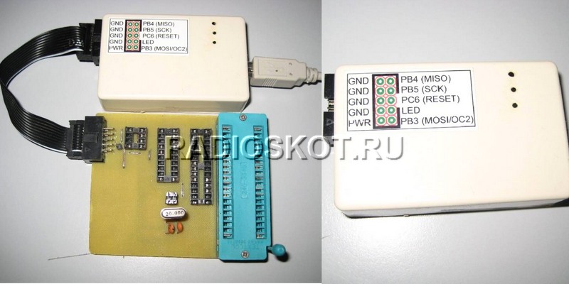
The programmer is based on the Objective Development driver and is fully compatible with the original ATMEL AVR910 programmer. Description of the device. The fuse protects the power lines USB port from accidental short circuits in the power supply circuits of the programmer. Diodes VD1, VD2 are silicon rectifiers, they are designed to lower the power supply of the microcontroller to 3.6 V. According to the documentation, the controller can operate at this supply voltage up to a frequency of just over 14 MHz. LEDs VL1 (" RD"), VL2(" WR”) signal the current actions of the programmer and indicate the read and write modes. LED VL3 (" PWR”) indicates that power is being supplied to .
Jumper J1 - ( MODify) serves for initial programming control MK programmer. When it is closed, an external programmer is connected to the ISP connector and the control program is loaded into the MK. After programming the control MK programmer, this jumper must be opened and the jumper J2 - NORMal closed.
Jumper J3 LOW SCK lowers the clock frequency of the SPI port of the MK programmer to ~ 20 kHz. When the jumper is open, the SPI frequency is normal, when the jumper is closed, it is reduced. You can switch the jumper on the go, since the programmer's MK control program checks the status of the PB0 line each time the SPI port is accessed. It is not recommended to switch the jumper while the process of writing/reading of the programmable MK is running, because, most likely, this will lead to distortion of the written/read data. Jumper J3 is introduced for the possibility of programming MK AVR, clocked from an internal 128 kHz generator.
Resistors R10 - R14 are designed to match the signal levels of the microcontroller of the programmer and external circuits (programmable MK or other programmer). The clock frequency of the SPI port of the MK programmer with the open jumper J3 is 187.5 kHz. This allows the controllers to be programmed with clock frequency from about 570 kHz for ATtiny/ATmega, 750 kHz for 90S and 7.5 MHz for 89S. Controllers are programmed from 10 to 30 seconds (using the AVRProg v.1.4 utility from the AVR Studio package) along with verification, depending on the amount of FLASH memory and clock frequency.

A square wave with a frequency of 1 MHz is output to the LED output of the ISP connector to "revive" the MK, which had erroneously programmed fuse bits responsible for clocking. The signal is generated constantly and does not depend on the operating mode of the programmer. The programmer was tested with the programs AVRProg v.1.4 (included in the AVRStudio package), ChipBlasterAVR v.1.07 Evaluation, CodeVisionAVR, AVROSP (ATMEL AVR Open Source Programmer). For the normal functioning of the controller in the circuit, it is necessary that the bits be programmed (set to "0") SPIEN, CKOPT, SUT0 and BODEN. Usually microcontrollers coming from the factory, i.e. new, have already programmed bit SPIEN. The remaining bits must be unprogrammed (set to "1").
Instructions for installation and operation. Flash the controller. Connect the freshly baked programmer to the computer via USB. The operating system will find a new device - AVR910 USB Programmer, when prompted to automatically find the driver, refuse, and specify the path to the inf file, depending on the operating system installed on your computer.

The forum contains all the files, as well as the printed circuit board for our avr programmer. Here I will show the technology of assembling the AVR USB programmer and packing it into the case. First, download the archive and make a printed circuit board.

Then we solder all the details on it. I could not find a small quartz, so I soldered a large one, but on long legs, so that later I could bend it so that it would not interfere when installing the board into the case. Next, we select a suitable case, I had it ready.

We adjust the board to the case, make all the measurements, drill holes and here is the finished device for you, with a universal board.

If there is no special measuring equipment, you can check using the LED. The LED is connected anode to the LED pin, cathode to any GND pin of the ISP connector. When power is applied, the LED should glow in the “half-light”. When the legs of the quartz oscillator are closed with tweezers, the LED should either light up in “full heat”, or there should be no glow.
An assembled programmer with a correctly programmed microcontroller does not need to be configured without errors. But if the RESET input of the programmable MK is pulled up to the supply voltage by a resistor, then the resistor value should not be lower than 10 kOhm - this is due to the reduced supply voltage of the control controller in the programmer circuit and the introduction of limiting resistors on the ISP connector bus.
Discuss the article PROGRAMMER AVR USB
For radio engineers who love to design electronic appliances, from time to time there is a need to use microcontrollers in their developments. Applications of these semiconductor devices
opens up great prospects for radio engineering. Microcontrollers are produced by only a few companies, the leaders of which are MicrochipTechnology, ATMEL, ARMLimited. Main Feature such devices is the need for their software firmware. This is what programmers are for. Today there is a huge choice various types programmers, however, the price of such products is very high, and not every radio amateur can afford to purchase such a device.
In this article, we will consider a USB programmer (AVR) based on the Atmega 8 control microcontroller. This product is simple enough for a radio amateur to assemble it on his own and not spend a lot of money on a branded product. The USB-programmer (AVR) we have chosen has a minimal microcontroller binding, which allows us to assemble a very tiny device. Such a product does not take up much space, it has a regular flash drive. The USB programmer (AVR) in its circuit contains a microcontroller case type - TQFP 32 (not to be confused with the DIP case type, since they have different pinouts). A diagram of such a device is shown in the photo.

Let's proceed to the description of the device circuit. Jumper J1 is used when it becomes necessary to flash a microcontroller with a clock frequency below 1.5 MHz. If desired, this jumper is easily excluded from the circuit; for this, the 25th output of the controller sits on the ground. In this case, the AVR-USB programmer will always operate at a reduced frequency. It should be noted that programming does not take more time, but of course it's up to you to decide. Zener diodes D1, D2 are used to match the level between the USB bus and the programmer. The blue LED indicates the readiness of the device for programming the microcontroller, the red diode is on during programming. The circuit has an IDC-06 connector with pinouts that match the ATMEL type of the 6-pin ISP connector. The power contacts of microcontrollers are output to the specified connector, it is taken from the USB port personal computer, therefore, you must be careful not to allow programming of the control controller using the same connector, for this it is necessary to connect the Reset contacts on the controller and on the connector (shown in red dotted line in the diagram).

The speed reduction jumper of the programmer and the microcontroller connector are located on the end of the device. This is what a USB programmer (AVR) is, as you can see, everything is elementary.
After assembling the device, it is necessary to flash the control microcontroller, for this I recommend using the PonyProg program. When programming, we start the crystal for operation from an external clock source at 12 MHz.
The USB programmer for AVR described in this article works with all AVR type microcontrollers, allows you to flash them, view the recorded contents of the device, erase chips, and change the configuration.
In this article we will describe the "step by step" manufacturing steps USBasp programmer for AVR microcontrollers. In separate articles, we will describe the installation of drivers for operating Windows systems XP and Windows 7 (x64/x86). At the end of the post there is a link with the necessary documentation for making a DIY USBasp programmer.
The USBasp programmer, due to its ease of manufacture and the use of inexpensive and widely available components, has become very popular among radio amateurs. Its operating parameters are not inferior to professional and expensive AVR microcontroller programmers.
Key features of the USBasp programmer
- Works with multiple operating systems- Linux, Mac OS X and Windows - including Windows 8!
- Does not require external power.
- Able to program at speeds up to 5kB/s
- There is an option (Switch 2) to reduce the programming speed - for processors with quartz less than 1.5 MHz
- Provides programming voltage (Switch 1) 5 volts
- Indication of programmer operation using LED
Before starting work, it is worth familiarizing yourself with the sequence of all actions performed, namely:
- Selecting a diagram / drawing of a printed circuit board
- Transferring a printed circuit board pattern to foil fiberglass
- PCB etching in ferric chloride solution
- Hole drilling
- Mounting elements (soldering)
- Programming Atmaga8 programmer
- Connecting the programmer to a computer
- Driver Installation - Windows XP, Windows 7
- Selecting a program with USBasp support
There are many versions of the USBasp programmer, but they are all based on the master circuit, authored by Thomas Fischl. The firmware of the microcontroller of the programmer is also his authorship.
Original programmer circuit:

In this case, the original scheme was chosen as the basis. Since the use of jumpers in original scheme not very convenient, it was decided to use DIP switches. Some resistor values have also been changed.
Moreover, in the original scheme, the TxD and RxD lines are routed to the ISP connector, although this is not necessary (more precisely, they are not used in practice).
Below is the diagram with the changes made:

Building a USBasp programmer
There are many versions of the printed circuit board of this programmer, some can be found on the USBasp official website. However, it was made on the basis of the above scheme.
Unfortunately, due to the use of DIP switches, the board design became a little more complicated, which resulted in the use of 2 short jumpers, in order to keep the PCB still single-sided.
Below is the PCB result:


As you can see in the figure, SMD elements were not used in the programmer. The empty space on the board is “filled” with the mass field, mainly in order not to corrode a large number of copper, as well as reduce the effect of interference on the programmer.
List of elements used in USBasp programmer:

- R1: 10k
- R2: 180
- R3: 100
- R5, R6: 68
- R7: 2d2
- C1, C2: 22p
- C3: 10µ
- C4: 100n
- LED1: Red LED 20mA
- LED2: Green LED at 20mA
- D2, D3: 3.6V zener diodes
- X1: USB connector type B
- SV1: IDC-10 socket
- Q1: Quartz 12MHz, case HC49-S
- SW1: Dip switch three position
- IC1: Atmega8 ( NOTE: Do not use the Atmega8 microcontroller - PU due to its maximum clock frequency limitation to 8 MHz!)
The transfer of the printed circuit board pattern of the USBasp programmer to fiberglass was performed using the LUT () method. We will not describe how to do this, since there is a lot of this information on the network.
Let's briefly say that first a 1:1 scale drawing is printed on glossy paper, then it is superimposed on the cleaned and degreased copper side of the fiberglass and fixed with paper tape. Next, the paper side is carefully smoothed with an iron on a 3-ke. After the whole thing is soaked in water and gently cleaned of paper.


The next step is etching the board in a solution of ferric chloride. During etching, it is desirable to maintain the temperature of the solution at least 40 C, so we immerse the jar with the solution in hot water:

After the etching process is completed, the toner must be removed with acetone.


All that's left now is to drill the holes. After the board manufacturing process is completed, you can start soldering the elements of the USBasp programmer, starting with the jumpers.


Print-ready (in PDF format) the PCB drawing is at the end of the article. You can also find several options on the official website of the project.
First launch of the USBasp programmer
Now that all the parts are soldered, it remains only to “flash” the Atmegę8 microcontroller of the programmer itself. To do this, you need a separate programmer, it can be, for example, STK 200 (LPT port), STK500, etc. The LPT programmer is connected to USBasp via the IDC-10 connector.
Please note that the pin distribution in the connector of the original programmer (USBasp) is on the right, while in the version described in this article it is on the left:


The distribution shown in the figure on the right corresponds to those used by Atmel in their original programmers. This distribution reduces the risk of interference during programming in case of using long wires from the programmer to the controller, since each signal line is shielded by ground, except for MOSI.
During programming, turn on SELF mode by turning DIP switch No. 3 to the ON position. This makes it possible to program the Atmega8. After programming is complete, switch position (3) must be set to OFF.
The latest firmware version can be downloaded from the official website. We recommend the version for Atmega8, which is in the archive: usbasp.2011-05-28.tar.gz.
Please note that before programming the Atmega8, it is necessary to set the fuses, which have the following values:
- # for Atmega8: HFUSE=0xC9 LFUSE=0xEF
- # for Atmega48: HFUSE=0xDD LFUSE=0xFF

In case of successful programming, we connect the programmer to the USB connector of the computer, while the red LED should light up, and the computer should notify about the detection of new equipment.
Installing USBasp Programmer Drivers
The method of installing the programmer drivers is described in separate articles, there are also the drivers themselves. Below are direct links to these articles:
- Installing drivers for the USBasp programmer under Windows XP
- Installing drivers for the USBasp programmer Windows 7 x64/x86
Programs for the operation of the USBasp programmer
most popular program that supports the USBasp programmer is the AVRdude console program. There are also many derivative programs, the use of which is much more convenient. They are presented in the article Comparison of programs to support the USBasp programmer.
Well, it's time for us to build a USB programmer. For a long time I could not decide which programmer we would assemble. I chose according to the criteria of simplicity of design and ease of working with them, but I didn’t like anything. Chance helped me choose a programmer. Or rather, I did not choose it at all - I accidentally assembled it myself without suspecting it!
And it was like that. A few posts ago we built a USB to UART converter on the ATtiny2313 (we even improved the PCB). Even when choosing a converter circuit, I planned to obtain devices for various purposes on its basis (by filling in various firmware). At that time, I did not suspect that this converter could be used more widely than I had planned. Seeing USB circuit programmer - USBtiny on ATtiny2313 I realized that I already have a ready-made programmer!
Looking at the diagram made earlier, the USB to UART converter(homepage)

and a diagram of the USB programmer USBTiny(Homepage) 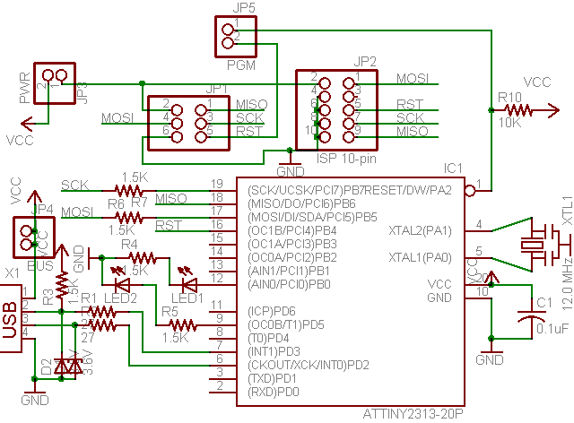
you can see that it's the same pattern. The differences are minor - there are no signal LEDs and a few resistors. In order for the converter to become a USB programmer, you just need to flash the microcontroller new firmware and make a cable to connect.
Now everything is in order.
1 First you need to assemble the converter(if you haven't collected it yet).
Here is a picture of the converter PCB:
If you're interested, here it is.
The assembled converter looks like this:

2 We slightly modify the board
In order to provide all the necessary signals for programming, we solder protective resistors with a nominal value of 100 Ohms in the line of legs 12, 16, 17, 18, 19 (the value is not critical - you can vary it).

3 Now you need to flash the microcontroller.
The lines for the programmer are brought to the common connector of the board (except for the reset - it costs separately).
You probably do not need to say that you will need a programmer to flash the microcontroller. In haste, you can assemble and flash with.

The circuit diagram is simple.
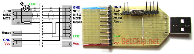
Of the features - I took out the indicator LED and the ballast resistor for it for a fee on the connector - this is so that the board can be used for other devices without soldering (well, it's cooler - the LED blinks right in the connector :)). In addition, the Vcc line is separated from the common connector - this is in case the device being programmed is powered not from USB, but from its own source (which, in principle, is desirable). It is desirable to shield signal lines (SCK, MISO, MOSI) (for example, by alternating signal and ground lines in a loop). The length of the train should not be made large - up to 50 cm, no more. If you need to program a remote device, you can always use a USB extension cable - this is more reliable. Here is my finished string:

5 The programmer is ready now you need to install the driver in order for Windows to work with it (for Mac OS X & Linux, it seems, no driver is needed at all). Everything is simple here:
5.1 Download the driver, unzip it.
Drivers page

5.2 We insert our programmer into the USB port.

5.3 A message will appear in the tray stating that a new device has been found.

5.4 The Found New Hardware Wizard will start.

5.5 Specify the folder with the driver in the "search location" box.

5.6 The driver installation process will go through. A window will appear informing you that the driver is installed. To check what we installed there, go to "My Computer / Properties / Hardware / Device Manager" and find our programmer there

Winda saw a new device and is ready to work with it.
USBtiny programmer supported by AVRDude, which means that many programming environments will work with it without problems. Another advantage of working with AVRDude is that there are many GUI shells for working with AVRDude from which you can choose the one that suits you (but more on that in the next article).
I have not worked with USBTiny before, but the reviews about it on the network are positive (it is distinguished by reliability and programming speed) - my test firmware confirmed this. ATtiny2313 is flashed in 10 seconds (this is with verification). The microcontroller is defined and programmed reliably - there was not a single error during my tests. Nice programmer!
Files for the article:
- UART-USB PCB drawing on ATtiny2313
- Firmware USBtiny programmer for ATtiny2313
- ATtiny2313 fuse bits for USBtiny
- Cable diagram for USBtiny programmer


