BiQuad (Biquad or zigzag antenna). Building a Biquad Antenna Double Square Antenna Wifi Diagram
Zigzag Antenna is very popular with radio amateurs due to its simple design, good repeatability and broadband. It is an in-phase antenna array of two diamond-shaped elements (RE) located one above the other and having one common pair of points power a-b(Fig. 1a).

On fig. 2, a and b show, respectively, the dependence curves of the traveling wave coefficient (TWF) with direct connection to the power points of a zigzag antenna of a 75-ohm feeder and the gain G (compared to a half-wave vibrator) on the ratios l / ^ and l / d, where l is the length of the RE side, ^ is the wavelength of the received signal, d is the diameter of the conductor from which the RE is made.

It is possible to increase the efficiency of a zigzag antenna with a reflector by building an in-phase array on its base. In this case, naturally, the antenna system becomes more complex and cumbersome.
Biquadrat is probably the simplest and most easily repeatable Wi-Fi antenna in the range.
With its simplicity, it has a good gain of about 10 dB. and can be used both independently and as a radiator for a parabolic antenna, while the gain can be > 20 dB.

The active vibrator is made of a copper core of an electric wire. The core can have a diameter of 1.5 - 2.5 mm.

A very crucial moment is markup. The resonant frequency of the antenna depends very much on the thoroughness of this operation. On a copper vein sharp edges caliper sponges are applied 8 marks through 32.9 mm.
According to the resulting marks, with the help of pliers, as uniformly as possible, we bend the marked copper core as shown in the figures:


The ends of the resulting vibrator are shortened by 2 mm and tinned:


We make a reflector - a reflector, the material can be foil fiberglass, tin, aluminum (at the end of the article there will be photos of a non-standard solution in the manufacture of a reflector).
An important role is played by the distance from the reflector to the vibrator; it should be 15 - 16 mm.

In the basic version, the size of the reflector is 110 X 123 mm.

Mounting and powering the vibrator can be done in several ways (depending on the availability of materials and imagination).
I use this option:


A tube (copper) of a suitable size is taken, a cut of 1 mm is made at one end, a hole is drilled in the reflector for the diameter of the tube, and a tube is soldered into it, the upper end should be at a distance of 16 mm. from the reflector, a 50 ohm cable is passed through the tube, the screen braid is soldered to the end of the tube.
Concerned earlier designs wifi antennas directed action. Bisquare, canned homemade rarities. People with enviable constancy are looking for a chance to get a better design. It was mentioned: instead of a traditional wire, it is better to take a PV1 wire of a similar section, which saves installed antenna from bad weather. A board with double-sided foil, which is often recommended to be used as a reflector, does not tolerate bad weather very well, is not protected by anything, it is problematic to supply the design with a special case. The wind load on the product will increase. Today's review is devoted to methods for improving the design. Do-it-yourself Wi-Fi antenna for any bad weather!
Important! Try using shrink wrap for protection. Put on a reflector “fur coat”, blow with a hair dryer. Soon the textolite will be tightly covered with a polymer film.
Bi-square Wi-Fi Antennas
The Wi-Fi antenna, built according to the biquad scheme, is formed by a grounded reflector, a figure-eight emitter with right (90 degrees) angles. It turns out something resembling trendy glasses with a thin bridge in the middle. The lower half is planted on the ground, the upper half - on the signal core of the cable RK - 50.
True, the antenna for Wi-Fi will be smaller in size. The side of the square along the midline of the copper core of the emitter is 30.5 mm. So, the figure eight is 1.5 (half the length of the side of the square) cm from the reflector and is parallel to the plate. In our case, the getinax fee is bad because it is difficult to get. The reflector is just a plate of conductive electricity metal. Tin, steel, aluminum will fit. Given the size of the emitter, you can make a WiFi antenna reflector using a 5.25 inch laser CD.
Biquadrat Kharchenko
The internal reflective aluminum layer is designed so that the laser beam does not lose energy on the surface. In addition, there is a hole in the center for the N-connector. It remains to open the protective plastic shell, put the reflective layer on the screen of the PK-50 cable. Please note: if the N-connector is not 1.5 cm away from the reflector with the emitter, the reception conditions will worsen. It is necessary to achieve the indicated position by placing thin metal washers or in place.
We remind you: the bi-square figure eight bends from the middle by turning 90 degrees. Both ends of the PV1 1x2.5 cable will return to the point. The thickness of the wire is 1.6 mm in diameter, between the centers of the core, the side of the square is 30.5 mm. The ends sit on the connector screen, are combined with a reflector (CD), the middle part will serve as a signal pickup. The radiation pattern of the device is sharply narrowed, equipped with one main lobe, which we direct to the signal source. If the case is in a room, you will have to experimentally find a reflected beam located in almost any direction.
The reflector will protect against neighborly interference, increase power. Blocks the multipath effect, which is of little use to the equipment. Homemade antenna Wi-Fi only accepts from a narrow sector. Thanks to this, we will connect the houses opposite by a network, which would not be possible with the supplied access point.
Please note: in other cases, there may not be an input connector on the case for connecting an antenna. Such access points are equipped with built-in metal circuits that receive radio waves. Traditionally, they look like intricate flat figures on the inside of the case. We'll have to unsolder the built-in antenna.
A capacitor can stand nearby, the capacitance serves the purpose of compensating for the compression ratio of the circuit. The built-in antenna is small, powerless to form a full-fledged device for receiving radio waves. The defect is neutralized by a tuning capacitor.
The element is not needed, because a full-sized antenna for a Wi-Fi router does not need to be compensated. Tear the homemade switching circuits above the capacitor. Do not use a typical 100W soldering iron when doing the installation. It will burn the electronic components of the board. You will need a small soldering iron equipped with a 25W needle tip.
The weight of the CD is small, the wind load is low, in contrast to the bulky design and will not kill anyone from below with a falling getinax board. It is recommended to avoid placing products in the sun, but in our case, the recorded information does not play a great role. If desired, seal the N-connector, extending the life of the solder joint. A special gel compound is used during installation printed circuit boards. Similar ones are produced by the Allur company (St. Petersburg). A few words will explain how to make a Wi-Fi antenna more powerful with your own hands.
Bisquare antennas
Prologue: 2 weeks, I couldn’t find the reason for it, then I turned the antennas into a vertical one and got 20 Mbit per 5 km, instead of horizontal 4.
Vampiresh, forum member Local networks Ukraine (spelling copied).
Before you buy a Wi-Fi antenna, think about it: theory shows that emitters arranged in rows narrow the radiation pattern in the direction perpendicular to the line along which to line up the elements. Translated into Russian, it means: if our houses are separated by 100 meters, the width of the antenna viewing sector for implementing the Wi-Fi communication channel barely exceeds 15 degrees. Useful power will be directed to the window of a friend (it will only harm the inhabitants of the apartment!). To implement the circuit, use a dual biquad antenna. You can increase the speed if you give the same to a friend on DR!
How to make a Wi-Fi antenna so that it does not interfere with neighbors. You can protect yourself from uninvited guests by changing the channel, polarization. There are three ways to protect the channel with the antenna configuration:
- Frequency selection.
- Direction selection (beam narrowing).
- Choice of polarization.
Usually, when there is Wi-Fi provided by the provider, the values \u200b\u200bare set by the communication provider, the client has to obey, but if you have your own equipment, the situation is different. We can put the antenna on vertical polarization if the neighbors use horizontal polarization. Our equipment will stop seeing each other. Can be done unilaterally or negotiated. Antennas will be needed like a biquad, set aside.
Television operates on horizontal polarization, communications on vertical polarization. Just a tradition, it is convenient to keep the walkie-talkie pin perpendicular to the ground when you speak. In this context, it is beneficial to use vertical polarization, usually found in routers. We offer a simple rule:
- Position with a friend opposite the antenna on the windows in the same way. Spatial compatibility is provided, which is a subspecies of electromagnetic. Microwaves, telephones, a mountain of 2.4 GHz interference equipment have been released. Position the antennas equally, vertically, horizontally, tilted. Experimentally look for the position at which the speed is greatest.
The promised novelty: a design of four squares lined up in a row. The radiation pattern will become narrow in the direction perpendicular to the formation. Copper wire or solid wire with a cross section of 2.5 mm 2 50 cm long. We recommend taking it with a margin. If a standard biquad Wi-Fi antenna for a laptop is an in-phase array of two frames, in our case there are four frames.

Frame for dual biquad antenna
When the wave moves, the current in neighboring squares is directed oppositely along the contour. Due to this, the effect of the impact of the field is added up. Now we need to get four in-phase squares. Find the middle of the wire, make a 90 degree bend. We measure 30 mm, make bends on each side in the opposite direction. We retreat twice as much, again bend in the first direction. You get a large letter W. Another 30 mm - bend the edges down at 90 degrees. One half is ready.
We do the second in the image and likeness so that the ends return to the point of the initial bend. Please note that it is not in vain that we recommend using a wire with a PVC sheath - the two crosshairs in the figure are mutually isolated.
We cut off the excess wire so that the ends do not reach the first bend by two or three millimeters. A Wi-Fi antenna for a computer requires a reflector, a good piece of foil textolite or a standard flat sheet will do. We use the N-connector for the connection.
The emitter is separated from the reflector by 1.5 cm in area. We plant the ends on the ground, the middle - on the signal core (cable for Wi-Fi antenna RK - 50). To reinforce the edges of the figure, use a ceramic or plastic tube. For fixing, electrical insulation, use glue, sealant. The street version is recommended to find a plastic case. Take a smaller distance between the homemade antenna and the receiver.
The next meeting will discuss Wi-Fi radio.
This article details the construction of a biquad antenna. The Biquad antenna is easy to manufacture and provides a reliable 11dB gain with a fairly wide beamwidth.
Trevor Marshal has a website with information on using a biquad as a irradiator for satellite dish Primestar, with very good results. I decided to try and use the biquad as a feed for a 24dB parabolic antenna.
Note that the photos on Trevor Marshall's website do not clearly show the construction of the biquad - especially the way the vibrator is connected to the cable. Many people (myself included) have built biquads incorrectly based on photographs of him and have come to the conclusion that his performance is very poor.
Use the photos of my biquad antenna below, and refer to the websites listed in the reference section at the end of this page for additional information about the correct construction of the biquad.
Materials used
I used the following materials:
- 123mmx123mm piece of foil textolite
- 50mm 1/2″ copper tubing
- short length of CNT-400 or L MR-400 coaxial cable (~300mm)
- 250mm 2.5mm2 copper wire (diameter approx. 1.5mm)
- N connector
Note that you are not required to use PCB for the reflector. You can use any electrically conductive material that reflects radio waves (that is, any metal plate).
I have also heard of people using the CD-ROM as a reflector because the foil on the disc reflects radio waves.
Reflector
Cut off a plate measuring 123 × 123 mm from foil textolite.

Cut off a 50mm piece of copper tube and polish it (including the inside to ensure a good connection to the cable).


Drill a hole in the textolite so that the resulting tube fits snugly in the hole. I found that it is most convenient to do this with a drill, having previously drilled a hole.

Insert a copper tube into the hole with a cutout to the copper side of the textolite. The copper pipe should protrude 16 mm from the hole.

Solder the copper tube to the PCB to get a good electrical connection.

To solder the tube, a sufficiently large soldering iron power is required. I have found that a small gas burner works well for this purpose.
Making a vibrator
Vibrator made from cut copper wire, bent in the form of two squares.
Note that the lengths of each of the "sides" should be as accurate as possible (length measured from the center of the copper wire to the center of the copper wire).

I used copper wire from a piece of electrical cable with a section of 2.5mm 2 . This cable is about 1.6mm in diameter, slightly larger than the 1.2mm recommended by Trevor Marshall. This should not have much effect on the characteristics of the antenna.

Remove the insulation, cut off a length of 244mm and straighten it well

Measure the middle of the wire, and make a 90 degree bend. The bend radius must be minimum

Measure the middle of each half, and make two more 90 degree folds so that you get the shape shown in the photo below.

Once again measure the middle of each section, and make another 90 degree bend so that you get the shape shown in the photo below.
 One more twist
 Do the same on the other side to bring the antenna into a biquad shape.

Check that each side measures 30.5mm and is level. You may need to shorten the wire a little.
Assembly
The vibrator should now be attached to the reflector. Note that only the two "ends" of the copper wire should be connected to the copper tube - the center of the copper wire must not touch the copper tube (This is what the cutout in the copper tube is for).
The wire vibrator should be at a distance of ~15 mm from the reflector. Testing the antenna by varying the spacing between the vibrator and the reflector, I found that ~15mm spacing provides the lowest SWR (test results available here).

clean up coaxial cable by 30mm. 
Unravel the outer braid, strip the center conductor and cut it so that it protrudes 4mm

Insert the cable into the copper tube so that the center strand of the wire is flush with the end of the tube, and solder the center of the vibrator to it. Make sure that the center of the vibrator does not touch the copper tube.


In order for the cable to be firmly held in the tube, it must be crimped with a cable crimper.


Now it remains only to install the connector on the other end of the cable.
If desired, you can add spacers at the ends of the vibrator to increase the mechanical strength. How to perform them can be found on the page about the antenna.
If you are going to install the biquad antenna outdoors, I would recommend that you place it in a weatherproof enclosure to prevent corrosion and water intrusion into the cable.
Many people have successfully used microwave food containers for this purpose.
Testing
Carried out the first test of a biquad antenna as a 24dB feed of a parabolic antenna. The results were quite satisfactory to me.
I was also able to get a 10km connection using just a biquad connected to a 30mW RoamAbout Wi-Fi card.
Some more detailed testing with multiple antennas, including the biquad shown above, indicates that the biquad has a gain of 11-12dB.
A friend has access to some antenna test equipment, and has performed some of the biquad tests shown on this page.
The biquad radiation pattern shown below shows a ~50 degree beamwidth.

Options
Many people suggest that the distance between the vibrator and the reflector should be 1/4 wavelength (ie, 30.5mm) instead of 15mm. However, test results indicate that the biquad's SWR is minimal when the distance between vibrator and reflector is 15-17mm. Increasing the spacing to 30.5mm increases the SWR, thus reducing the efficiency of the biquad.
If you need more antenna efficiency, then you can use an antenna that is just as easy to manufacture.
Usage
Using biquad to connect with another wireless device You must ensure that the polarization of the biquad is the same as that of the antenna you are connecting to. Note, by communicating with two biquads antennas you ensure that they are oriented in the same polarization.
Incorrect polarization of the antenna will result in loss of signal quality.
vertically polarized
horizontally polarized
The polarization is changed by rotating the entire biquad antenna 90 degrees.
The width of the antenna pattern is obtained in the range of 40-50 degrees. This allows you to use the biquad antenna for ward diving, allowing you to receive a signal without pointing the antenna at the signal source.
The latest version of the original is available at http://martybugs.net/wireless/biquad/
Instructions for making a "double" Bi-Quad (double figure eight) W-LAN antenna - 2.4 Ghz antennas for wi-fi.
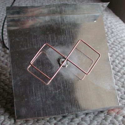
"Double Eight" is a continuation of Bi-Quad, which gain is 2 dB higher, i.e. is approximately 12 dB. When building, pay attention to the fact that the copper wires do not touch at the intersections. After construction, it is advisable to varnish the "double eight" to avoid oxidation / corrosion. How important it is to maintain a distance of 15 mm between the reflector and the copper wire is evidenced by the two photographs below:


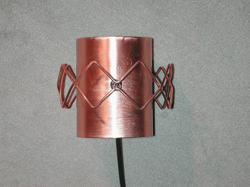
In order to avoid questions (there were in the first post), consider the construction of an antenna with a circular diagram, in this case something around 270 °.

First, a pipe with a diameter of 70 mm and a height of approx. 100 mm. Then bend a straight 6-element Quad from a copper wire and, using, for example, a bottle, give it an appropriate, curved shape. I repeat for those who do not read very carefully: the distance from the copper wire to the reflector in a circle should be 15 mm! It is important that the crossed wires do not touch each other!

Of course, this is not the only correct option for building such an antenna. The pie antenna can be made larger,


In this case, signal loss in antenna cable will be kept to a minimum.


And of course, about the main thing, about the size of the frame: whoever has a printer can download a document to be printed and it will be possible to bend the frame exactly according to the printed one: http://raffi.uddu.de/wlan/6erquad/6erQuad.doc
Ideally, it should look a little different, something like this:

but this is not so important, the main thing is that you can repeat the dimensions by printing. For bending "double eight" - extreme squares are not used. Those who do not have a printer use the following pattern to make a frame: the dimensions are given for a wire with a diameter of 2.5 mm

"Triple Eight" - another continuation of the "Double Eight", the gain coefficient of the "Triple Eight" can be 14 dB or a little more. This is how the painted "triple eight" looks like, in general, not bad:


For beginners! Please note that the posts supporting the antenna at a distance of 15 mm from the reflector must be made of dielectric material!
The "double eight" and the pie antenna discussed above can be mounted together in one housing:


From another.

The antenna is closed. For the manufacture of the protective case, a piece of plastic pipe with a diameter of 125 mm was used, which is used in plumbing, the cover is made of 2 cm plastic. The fixing top nut is made of plastic. You can paint in any color.


To avoid unnecessary questions: the antennas are not coordinated in any way, each is connected to a separate device.
I saw this on the Internet, to facilitate the bending of the frames, maybe someone will be interested:

ZY I would do it differently, much easier.
How to increase the reception range:
Selecting a WLAN device.
When choosing, pay attention to the fact that the output power (Pout.) is as close as possible to the permitted, i.e. \u003d 20 dB (in Russia it may be different, I did not recognize it). You can buy a device with a 14 dB output, but it can be used for not very large distances.
The next decisive factor is sensitivity. For the best modern devices, it is at the level of approx. -97dB. The higher the sensitivity, the better the device will be able to receive weak signals.
How do these values affect the communication range:
One device with Pout = 20 dB will be able to provide twice the reception range compared to a device with Pout = 14dB, i.e. a difference of 6 dB gives a double win. If we add to this that a device with a sensitivity of -97dB allows you to get a gain of 4 times compared to a device with a sensitivity of -76 dB, then the total gain will be 8 times.
In order to increase the communication range by 2 times, you need to raise 4 times output power, i.e. by 6 dB, and by 4 times - by 12 dB, etc.
How to keep the output power at 20 dB.
For example: you have a device with an output power of 12 dB, which is connected to the antenna with a 5-meter cable (the loss in the cable will be, for example, 4 dB), the antenna gain is 10 dB. We consider: 12 dB - 4 dB + 10 dB = 18 dB. Those. in this case, the antenna can be changed to another, with a gain of 12 dB.
Communication range.
If external factors do not interfere, then small directional antennas can achieve a range of 2 km (or a little more) in the line of sight. If you take a satellite dish, in which you install a WLAN antenna instead of LNB, you can establish a connection at a distance of 20 or more kilometers. In any case, this distance can be increased by using an antenna amplifier for the receiver, which will be difficult to install. the same cable is used for receiving and transmitting. There are, of course, high-quality intelligent amplifiers that detect when the WLAN device is transmitting a signal and automatically switch the output signal to the "transmit" mode for the duration of the output signal, but these "intelligents" cost decently. A cheaper alternative to this would be to put two antennas - one for reception, with antenna amplifier and the other for transmission. Even with the purchase of the necessary parts, it should be cheaper.


An interesting solution - a parabola was combined with a Bi-Quad based on a CD spindle.

P.S. I myself do not use WLAN, and not only because the 128-Bit-WEP-key is disenchanted in 1 minute, but simply not yet necessary. Therefore, I cannot share the joy of building an antenna.
Source - http://www.vallstedt-networks.de/
Today we want to offer you the design of a simple, inexpensive and reliable antenna, which can be assembled almost from scraps!
The operating frequencies of Wi-Fi and WiMAX are absolutely identical and equal to 2.4-2.7 GHz. The difference lies in the encoding of the signal and the power of the transmitter, but for our antenna this is completely unimportant. To make an antenna, we need to know the wavelength. According to the formula from the physics course, it is quite simple to calculate it. It is enough to divide the speed of light in vacuum by the frequency of the wave. Let's not bother you with long calculations. Let's just say that its length is approximately 124 mm at 2.4 GHz (the beginning of the operating frequency) and 111 mm at the end of the range at 2.7 GHz. To create an antenna that performs the same over the entire frequency range, we will make the side of the square equal to 30.5 mm, which is the quarter-wave band.
A bit of theory
The antenna consists of two parts: a reflector and a resonator. The resonator is itself a quarter-wavelength double square, while the reflector is the metal part to which everything is attached. Naturally, among radio amateurs this simple and affordable option antennas have been used for more than a year, and this system itself was invented a very long time ago. This antenna is capable of giving gain from +6 to +10 dB. Some sources also report that if used in conjunction with a parabolic mirror (ordinary satellite dish), then gain up to +20 dB can be achieved. For WiMAX, this means free Internet in the country.
Manufacturing

Let's start with the resonator. For it you will need copper wire with a diameter of 1.5-3 mm. You can get it anywhere, because in our time it is not a shortage at all. In addition to it, you may need a hammer, pliers, soldering iron, solder, ruler, rosin or soldering flux, preferably LTI-120, and hands growing from right places. We hope you have mastered the school geometry course well enough and know how a square should look. First, we take a piece of wire 244 mm long and mark it every 30.5 mm. Then you have to take the pliers and bend the wire at a 90 degree angle at each notch. Make sure that deviations in different directions are minimal and the wire does not bend anywhere in the other direction. See drawing for simplicity.

As soon as you have one square, make a second one, as similar as possible to it, from the other end. The angle between the sides of the squares should be 90 degrees. You should get a closed loop. The ends of the wire can be soldered together. Next, put aside the resonator in a groan and take on the reflector. It can be made from anything at all: from the wall of a case from a computer, an old piece of iron lying around, a license plate number ...

However, we recommend using a board made of foil textolite for this. Firstly, copper is used there, the resistance of which is lower than that of iron, and secondly, textolite is able to withstand almost any weather conditions, which allows you to hang the antenna right on the street. For this antenna, it is desirable to use a single-sided board 120x100 mm, however, as practice shows, 100x100 mm is also quite suitable. Here we also need a drill. You will also need an N type high frequency connector assembly. You must measure the diameter of the connector you have chosen and drill a hole in the center of the board to bring it out. The connector is inserted from the empty side, and its output is foil-coated. After drilling more holes with a small drill along the connector fasteners and screw it to the board. These screws are easy to find at any hardware store. We solder two pieces of the same wire to the inside of the connector and to the board itself so that the distance from the reflector to the end of any of them is 2.5 cm. Next, you must take the resonator and solder it to these legs. Try to make the reflector and resonator parallel to each other. The manufacture of the antenna is completed, and we are starting to connect and configure
Connection and setup
Of course, you will need to somehow connect the finished device to the modem. Please note that everything you do with warranty equipment, you do at your own peril and risk! The editors are not responsible for this.
Take off to start top cover modem. This should be done carefully, preferably with a thin screwdriver or scalpel. Starting at one end, near the USB connector, then, slowly prying off the cover, move forward until it opens on one side. Then repeat the same procedure, but from the other end. After removing the cover, you will see two small connectors sealed with protective paper. Take her off too! If you put the modem USB port down, then we need the left connector. Don't even touch the right one! Now you have two ways: either buy a branded pickdale (adapter), or make your own. We chose the second option, taking the antenna adapter from a small burnt TV tuner and modifying it a bit by removing the inner plastic ring. But if you don’t have such a thing, then it’s better to buy a branded one .. Then you need to connect it to the wire. The wire should be RG-6U, as the most suitable in terms of impedance. The shorter the length of the wire itself, the less signal loss will be. In this case, we put a regular TV plug on one end of the wire, perfect for our homemade pickdale. The screwed part of the high-frequency connector for connecting to the antenna was hoisted on the second. After that, we connect everything together. The branded pickdale has a special attachment to the modem, but we used a paper clip and two rubber bands. Despite the fact that the design looks rather flimsy, it has been in our editorial office for four months now.
Next, you should hang the antenna on the street. We used a mast from an active television antenna and its attachment. After that, you need to bring the cable to the modem and put everything together. Next, we climb out onto the ledge (be careful not to fall down!) And set up the antenna for the access point. This is done simply: you turn the antenna slowly in all directions and monitor the signal level. Having found the point where the signal will be maximum, you fix the antenna as strongly as possible and forget about its existence. We managed to achieve a signal of 15 dB where a modem without an antenna caught 3-4, sometimes 5 dB. Practice has shown that for radio amateurs such an antenna finished off at 2.5 km.

results
We managed to achieve a good signal in a place where there should not be a reception provider on the WiMAX card at all. By trial and error, we made an antenna that, in terms of its characteristics, is not inferior to commercially available branded ones. In addition, it is very versatile and is suitable for both Wi-Fi and WiMAX. The difference is only in the type of connected equipment. During testing, there were failures and malfunctions, but not through the fault of the antenna. The only problem was a crow that nearly threw the entire structure off the 12th floor. The signal turned out to be stable, and the connection speed increased significantly. The only trouble was that we lost the warranty on the modem. Although it probably won't be needed.
Good luck, radio amateur!
Biquad antenna (BiQuad) version No. 2
This is my modified antenna design. And I made the antenna completely from aluminum. Since it is not soldered, I fastened everything with bolts. The antenna is true to size. In practice, I did not use it, but after consulting with radio amateurs and those who made such antennas, they said that it should work!


