Wi-Fi antenna drawing for a laptop. The theory and practice of making a powerful directional and omnidirectional Wi-Fi antenna with your own hands
Now many people cannot imagine themselves without the Internet and Wi-Fi access points. To increase the signal power of transceivers, both standard and additional antennas. Standard antennas range in power from 2 to 9 dBi, approximately. They look like this:

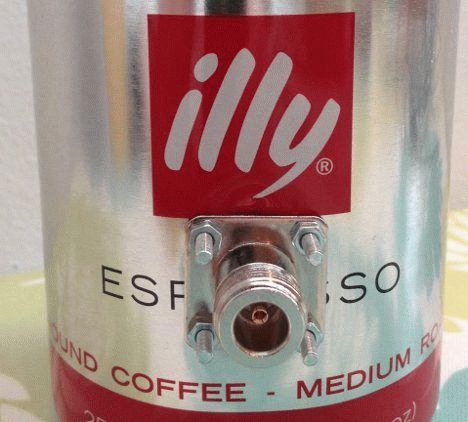
To increase the power and range of the directional signal, external antennas are used, which are installed outdoors and connected to the transmitting and receiving device with a 50 Ohm cable (not 75 Ohms!!!). They look like this:


In addition to 50 Ohm resistance, the connecting cable has specific tips:

Cables and lugs are available in an assortment in radio-electronic stores. But the antennas themselves are not cheap. If you look at what’s inside such an antenna, you’ll understand that it’s not worth the money:

After looking and monitoring the Internet, I decided to do it myself.
So, we will need:
– foil fiberglass, one-sided, 1.5 – 2 mm thick, dimensions 220 by 230 mm;
– jigsaw, with a metal file;
– drill or screwdriver;
– fine sandpaper, metal drills;
– a can of varnish;
– metal sheet, dimensions 270*240, thickness 0.5-1 mm;
– ferric chloride solution and container (tray for example).
So, stage one.
We mark and cut the fiberglass sheet to our sizes. We process the edges and clean the surface of the copper side.

The pattern of conductors and vibrators of our antenna will be cut out on the film. To transfer the film to the copper coating of the PCB, for convenience, ask either to immediately stick it on the cut or take the transport (advertising) film with you.
Stage three – gluing the pattern.
Before gluing the film to copper, it is necessary to degrease and allow to dry. Then we take it from a sheet of self-adhesive paper, cut out our pattern at right angles (if they have printed a lot of them) and apply advertising film to it (if we haven’t applied it at the company). Peel off protective film and remove the unnecessary part of the pattern, the background. We glue everything that remains onto the copper part of the PCB, smoothing it out and preventing air bubbles from forming. It will turn out like this:

Stage four.
Prepare a container of suitable size. We dilute ferric chloride in a proportion of approximately 100 g per 0.5 liter of water, heated to 60-65 degrees Celsius. We dismantle the advertising film. We lower our structure with fiberglass to the bottom of the container. Periodically fidgeting with the workpiece along the bottom of the container, we wait for the end of etching of the copper layer. When finished, rinse under running water and wipe dry. It will turn out like this:

We remove the self-adhesive. Next, in the round polygon, we drill a hole for the central pin of the connector for the cable. We take a can of varnish, open it in several layers and dry each one. Then we carefully clean and tin the soldering area.

Then, in the corners of the PCB and the metal plate, we drill four holes to connect like a sandwich, but with a gap. The distance between the copper layer and the beginning of the metal layer is 5mm.

The connector was first secured with a nut to the plate, and the plate to the screen surface.
Hello, dear reader! Today I will tell you how I made a powerful WiFi antenna with your own hands. Of course, my hands are golden, they just grow from the wrong place, but that didn’t stop me either. First, let's look at the so-called antenna gain. Do not worry! I will not use abstruse phrases or operate with any complex terms, but this needs to be dealt with.
This value is measured in isotropic decibels and is designated as “dBi” or “dBi”. You don’t have to remember the phrase, but the letters are worth remembering. Home routers usually have low-power antennas of 2-4 dBi. But as practice shows, in country houses or large office premises this indicator is not enough.
So today we will do homemade antenna from 10 to 20 dBi. There is no point in doing more and more powerfully. The thing is that with increasing amplification power, the signal beam becomes more directional and narrow. And the coverage radius becomes smaller. Take a look at the picture above. That is, it is possible to catch such a signal, but it is much more difficult, since the beam becomes too narrow.
Such antennas are also called directional. They can be constructed if you need to combine, for example, two country houses into one network via a bridge. Moreover, if they are located at a distance of up to 10 km.
Now let's look at frequency. Modern routers have two bands: 2.4 GHz and 5 GHz - this is the frequency of data transmission. It’s clear that the latter range has greater speed, but it also has one minus. As you probably remember from 7th grade physics, the higher the frequency of the wave, the faster it decays. That is, the coverage radius at 5 GHz is clearly lower.

After much thought, the best option is for home use The choice fell on a square antenna. It has such a shape that the gain can be increased to 20 dBi. And even with such power, the signal beam will not be so narrow. For the home, it will act as an omnidirectional antenna with a large radius.
In the second chapter, I will tell you how to make a powerful Wi-Fi antenna-gun for a router with your own hands. The panel antenna will significantly amplify the adapter's signal, but in a narrower direction. I will also talk about its further use at the very end.
Instructions for strengthening Wi-Fi at home

- We need to make a mount on which our antenna will sit. I still have some old CD packaging. Take and cut off the core approximately slightly above the middle. After this, you need to make small holes with a round needle file. So that you get 4 notches in the form of an even cross.

- Now you need to take a piece copper wire with diameters of 2-4 mm and make a resonator out of it. It will act as the main scatterer of the radio wave beam. Now, using pliers, you need to exactly make 2 squares with an edge length of 29-31 mm. The most important thing is to make sure that there is free space between the corners of contact of the squares.

- And so now we need coaxial cable. We solder the core to one corner, and solder the braid to the other end.

- We coat the bottom of the box with glue and glue the disk there. It will serve as a reflector of the radio wave beam. You can, of course, glue foil, but the disc looks more aesthetically pleasing. Now we carefully push the wire into the hole and also glue the squares to the semicircular grooves that we made earlier.

- We also seal the top with glue to ensure the reliability of the structure.

- We seal and back so that the wire does not break out. You can glue one wire, fill everything with glue - no need.

- Now you just need to connect the coaxial cable connector to the SMA port, to which the antennas are screwed. Everything is simple there, we solder the central core to the center of the SMA, and the braid to the outer part.

- For those who like to solder, you can open the router and directly solder our antenna to the board. But you need to understand that this is quite unsafe for the router, and if you don’t understand this, then you shouldn’t bother. Plus, you can damage the board itself if you don’t have the right soldering iron.

- In the end, you should end up with something similar to my “homemade” one. It doesn't look very good, but it penetrates walls at a frequency of 2.4 GHz - with a bang! For big country house It will do just fine. At correct installation It will be great to catch even if you’re not on the street.
Long distance directional antenna
I’ll say right away that this antenna is more powerful, but as I said, because of the power, the beam becomes more directional and narrow. Therefore, it should be used to connect several networks over the air. It can even be used as a repeater. The Wi-Fi gun will be able to hit a distance of up to 10 km.
It is done quite simply and all materials can be purchased at any radio store. However, its use is large outdoor or external, for sending a signal over a long distance. But you decide how to use it yourself. To build a bridge, you need to make a second one, which will also act as a receiver.

Here is the diagram according to which we will make our antenna. I’ll tell you right away that you need to do it as accurately as you can, according to the drawing. If there are strong deviations from the sizes and distances between the plates, then the connection will be worse. Also one more point - all sizes are designed to distribute 2.4 GHz waves.

- We cut even circles from a sheet of copper, and drill a hole in the center for a hairpin. We will also need nuts to match the size of the stud.

- Using a straight edge, start screwing the discs. Try to make it as close as possible to the diagram. Start screwing with small discs. On the last two you will need to make holes as in the picture below.

- Now we need any old antenna from under the router. You can also use a working one. Remove the top cap from it and cut off the main part. We also remove the rubber part, under which there will be a metal dome. We carefully cut it off, and under it you will see the wiring that we need.

- Remember those holes we made? - the wires need to be pushed into them at right angles and soldered to the plates, as in the picture below.

- Next, the antenna can be screwed to the router. But if you use the cannon as a bridge, then in this case it must be installed on the roof or on the street. Then you can solder a coaxial cable instead of this antenna. And for this case we will need a second pair of holes, which we for some reason forgot about.

- I had to widen the hole a little by drilling with a thicker drill bit. Next, I simply inserted it into the hole, but soldered it not to the first disk, but to the second, which should also have a second hole. Now the wire will need to be secured with something, you can wrap it with electrical tape or something else. Here you have some space to think.

- We put it on the roof. If you catch a second network from another house in this way in order to take Internet and network resources from there, then the antenna will need to be clearly turned exactly in the direction where a similar antenna will be located. A bridge can be made using two routers.
As practice has shown, such an antenna is powerful enough for suburban use and can penetrate up to 10 kilometers of direct range. You just need to take into account the obstacles that will dampen the signal. Therefore, it needs to be installed as high as possible. Also, do not forget about thunderstorms and lightning, so in addition to it, you need to install a lightning rod.
Purely theoretically, you can attach a TV to such a long-range device and use it to catch channels. If we go deeper, it can enhance the reception of any signal for a phone, laptop, etc.
Settings Wi-Fi networks demonstrates quite a lot of nuances. I came across someone trying to share the Internet with home users. One computer is connected to the provider via cable. An access point mode is created, a security protocol and a password are selected. Home users use the Internet in parallel. The technique does not work, thanks to the provider using a private line. The exit is located. The obstacles that stand between people and high-speed Internet are powerless to prevent a homemade Wi-Fi antenna from improving signal reception and transmission; communication range and speed naturally increase.
Purpose of homemade Wi-Fi antennas
Antennas adorn many devices. Let's list:
- Tablet.
- IPhone.
- Laptops.
- Wi-Fi modems.
- Wi-Fi routers, access points.
- Cell towers.
A homemade antenna for a Wi-Fi adapter will expand the capabilities of electronics. The access point is distinguished by its ability to transmit the signal omnidirectionally. The power spreads, filling the azimuths. By supplementing the access point with a special external purchased, homemade antenna, it can impart directional properties to the radiation. Will increase the range of reliable reception in the selected azimuth.
Stop breaking your smartphones by connecting an external antenna and assemble it yourself for an access point. Most antennas sold in stores have a circular radiation pattern, radiating equally, omnidirectionally, dividing the power by azimuth.
Powerful homemade Wi-Fi antennas have a much smaller field of view and will provide more reliable reception in some cases. Reflector-equipped devices have a radiation pattern with one central lobe. Remove the reflector and you get a figure eight. There will be a dead zone in the plane of the emitter; there will be no signal. A homemade antenna for a Wi-Fi router is unable to receive directional signals. The access point installation scheme is as follows:
- The device is connected to a computer (electrical network).
- The channel is selected.
- The setting is carried out at full power.
- The protocol type is selected.
- The password and network name are set.
People walk around happy with the new accessible point. Let's take a closer look at the process; let's take a moment to grab a soldering iron and pliers. Like a transmitter radio-electronic device, antenna, router have a certain peak of capabilities in the middle of the range. For example, on 2.4 GHz there are often 14 channels. The power of the transmitted signal is higher in the middle, for example, the sixth channel. Although each line occupies 22 MHz of the spectrum, the measurement is carried out at a field level of 0.707 (√2/2) maximum on both sides of the carrier frequency.
For reference. Determined by the modulation type, sometimes only the pilot signal remains, one band. Rectangular pulses, computer signals are just like that, have a pronounced maximum, a bunch of side lobes. As a result, the spectrum width of the real signal is infinity. The cyclic voltage band is limited, to which the process emitted by the Wi-Fi protocol does not come close.
A homemade omnidirectional Wi-Fi antenna does not the best option. Nothing will change. Homemade directional antenna Wifi is better, we will make it from wire, foil PCB, copper tube. They are so sensitive. Transmitted and received powers are concentrated in a narrow sector. It will improve the quality of transmission by carefully positioning users and the access point. You can judge how important the arrangement is by one curious case:
- The office called a technician. They said: between 12.00 and 14.00 the access point collapses. The technician took out a special device for estimating occupied frequencies and began the study. Similar programs are provided by the Android OS of smartphones. Use by selecting a channel before installation. Conduct research throughout the day for several days in a row, avoiding incidents. We bring to light what the master discovered: the neighboring office, separated by a wall, painted lunch. The workers took turns using the microwave (using the 2.4 GHz frequency). Poor insulation household appliances, the lack of grounding allowed the radiation to exhibit narrow-band interference at the frequency of the magnetron. The solution to the problem turned out to be simple: the access point was moved to the opposite end of the office.
If they had at hand a simple homemade Wi-Fi antenna from a beer can with a reflector, the heroes might not have known that there was a powerful source of harmful radiation next door. The reflector gives the access point directionality and will dampen the radiation coming from behind the wall. Another advantage of directional antennas, which we will make with our own hands today. By the way, when buying a microwave, try to determine safety. You need to plug the device into a grounded outlet and place it in the work compartment. cellular telephone, close the door, dial the number. The signal passes - harmful radiation from the magnetron will come out. Avoid sitting nearby. Let's discuss how to make a homemade Wi-Fi antenna.

DIY directional Wi-Fi antenna
Tools you will need:
- Soldering iron (solder, rosin, stand).
- Pliers.
- Small flathead screwdriver.
- Vernier caliper, ruler.
- Drill with a drill for a copper pipe.
Materials you will need:
- A piece of foil double-sided PCB as a reflector.
- Copper wire with a diameter of 1.2 mm and a length of 30 cm (only 26 cm of which will be needed).
- The RK-50 cable is not too long so as not to dampen the signal.
- A piece of copper tube 10 cm long for the RK-50 cable to pass inside.
Let's start with a copper tube. We saw through one end by 1.5 mm, removing two-thirds of the wall. The antenna will be soldered to the remaining piece. We create a bi-square contour with a side of 30.5 mm from wire. The size was selected based on the 2.4 GHz band setting condition.
In a similar way, you can make any antenna with a horizontal or vertical polarization signal. Including television. A homemade Wi-Fi antenna is suitable for a tablet, phone, or modem. If you know where to connect.
Please note that the side of the squares is given according to the middle section of the wire. Between the nearest edges there will be 30.5 - 1.2 = 29.3 mm. You can use it. We begin to bend, finding the middle. We use the edge of the ruler as a support and determine the state when the cut begins to balance. We make a bend of 90 degrees, this will be the point where the central core of the RK-50 will connect. We bend the wire, getting a “square eight”, both ends should return strictly symmetrically. We cut it a couple of millimeters short of the initial bend. We tin the ends and put the figure eight aside.
We mark the middle of the PCB and drill a hole so that the copper tube can barely fit in. We cheat both sides. We take a copper tube and tin the outer edge of the thin wall left by the first stage. The figure eight is 1.5 cm away from the reflector. We tin the tube in a circle, with the rim at the specified distance from the edge (without taking into account the thin wall). Solder the tube to the board, preferably at an angle of 90 degrees. We place both ends of the figure eight on a thin wall so that the initial bend does not touch the tube. Orienting the figure eights parallel larger side textolite at a distance of 1.5 cm. Now the reflector is grounded.
The RK-50 cable is pulled inside, the screen is placed on the copper tube, the core is placed on the initial bend of the figure eight. We mount the connector on the opposite end, simply solder the cut to the required contacts of the modem, telephone, or any other device. Let's start the test. The figure eight must be mounted vertically for horizontal polarization. If it works, we find silicone sealant that is not afraid of frost and precipitation, and fill the place where the cable exits with the antenna with a good layer. After hardening, the antenna will successfully withstand rain.
If you replace the wire with a thick conductor PV1 of a sufficiently large cross-section (2.5 mm 2), we will strip the braid at the point of initial bending and at the ends. A homemade Wi-Fi antenna for a laptop will be protected against bad weather. Today, heat-shrinkable materials are produced. The heated film tightly wraps the product, protecting it from the vagaries of bad weather.
Often, owners of large apartments and multi-storey private cottages want to freely use the Internet in any corner of their home. But the power of a Wi-Fi router is not always enough. To improve the quality of the network, an antenna for a wi-fi router can be used. It is not difficult to make a structure of any power and direction with your own hands.
By default, the factory-made router is equipped with omnidirectional antennas with a power factor of 2dB. It transmits the Internet in all directions at once. As a result, the signal “stretches” around the entire perimeter and weakens.
If there are one or two walls in the signal path, the pulse may not pass through them and there will be no network in the distant room. The situation will be corrected by a purchased or homemade Wi-Fi antenna for a higher-power router.
An omnidirectional antenna will not change the situation much, since the signal will still go in different directions.
It is better to make an antenna for a directional Wi-Fi router. The device will concentrate the network in a narrower sector and significantly increase the signal strength.
Owners of cottages who want to use the Internet not only at home, but also on the site, will need external antenna for the router. You can buy it, but it’s better to make it yourself. If it is a directional antenna, it will be able to cover a specific area with the network without distributing the Internet to all sides. It's not at all difficult to make.
DIY directional antenna
The most popular and easiest to make is a homemade antenna for a wi-fi router made from metal cans. It's easy to do, but it won't increase the signal too much.
If you need to improve the quality of the network in your home and surrounding area, you will need to make a more powerful device.

Assembly components

Biquad antenna

Do-it-yourself reinforcement with biquadrat
How to make a wi-fi antenna for a router:
- take a copper tube 10-11 cm long. Make a 1-2 mm cut from one end, removing part of the wall;
- From a piece of wire with a cross-section of 1.2 mm and 30 cm in length, we will make a bi-square contour with a working side of 3.5 cm. To do this, measure 15 cm and bend the wire 90 °. Next, we will bring the structure to a square eight and cut off the ends. They should not reach the middle of the wire by 2 mm. Let's clean up;
- Let's take a piece of PCB covered with foil and make a hole in the middle. The copper tube should fit into it with difficulty;
- solder the tube to the PCB at an angle of 90°;
- We will attach a copper structure to the wall of the tube so that its middle does not come into contact with the tube and does not reach the PCB by 1 cm;
- Let's drag a piece of RK-50 wire inside the tube. We’ll “plant” a vein in the middle of the figure eight. Solder the connector to the other end of the cable.
The resulting antenna to the router is mounted in a vertical position. Your own device is suitable for creating an 802.11 n connection in an apartment, yard or between houses.
Other homemade devices
Any DIY wi-fi antenna for a router is easy to make. Such a device can easily replace the 2-3 dB stock antenna included with the router and more than double the coverage area.
For outdoor use, an 8-10 dB remote antenna for a router made from satellite dish. To do this, you should upgrade the purchased dish by placing a homemade antenna in the center and connecting it to the router. The structure is installed at the highest place in the house.

Homemade wi-fi antenna
In addition to the plate, you can use a homemade product made from ordinary foil to make an antenna. But in this case, it will need to be protected from rain and wind by placing it in the attic or other closed place.
To stabilize the signal in a small room, you can make whip antenna. This is an analogue of the stock antenna that comes with the Wi-Fi router. Such a self-made device is much more powerful and distributes the network better.
To make it you need a piece copper wire and BNC connector. Having soldered the end of the wire to the “mother” of the connector, it is necessary to twist a ring from the wire 61 mm from the base. Then, after 91 mm, wrap another ring and after 83 mm from the last ring, cut the wire. The antenna on the wi-fi router is ready.
There are many other designs homemade devices. Which antenna option for a router to choose depends only on the user, his needs and abilities. Any homemade Wi-Fi antenna for a router will help improve the signal quality significantly.
A good gift is one that is made with your own hands (provided they are sufficiently “straightforward”). Well, the best router, probably, can only be homemade. Now there are many components that meet the mini-ITX standard. And in compact body, which you buy in the store, can be assembled WiFi router with your own hands, working with only one screwdriver, and your head too. Here we would like to list tips that will protect the developer from common mistakes made when choosing hardware components.
Storage device
The task looks like this: you need to assemble a computer consisting of a motherboard with a processor, a case with a power supply, and one expansion card (wired network card). It is better to buy memory of the smallest possible size (1 Gb), and let those cases whose design does not allow installing an expansion card be left with the seller. You also need to take care of proper cooling. The instructions for the case may indicate the TDP value of the CPU, for which it is not necessary to use fans, but if the TDP of your processor is higher, then the recommendation cannot be neglected. As hard drive It is better to use the following options:
- m-SATA (mini-SATA) SSD drive, if the motherboard is compatible with them.
- A device of the Intel Z-U130 class or its analogues from other companies (if you find it). Please note that such a drive cannot be installed on some boards due to mechanical incompatibility.
The most optimal SSD volume is 4 GB, and now we will talk about choosing a processor and board.
Choosing a mini-ITX motherboard
Our requirements would best be met by such a “motherboard”:
- The processor is already soldered, its TDP does not exceed 10 Watts (we will talk about choosing a CPU later)
- Compatible with m-SATA drives
- Power is supplied to the motherboard through a standard ATX connector (now there are power supplies with a power of 60-120 Watts that are fanless)
- The PCI-E x1 connector, or better yet just PCI, is present in at least one.
You will laugh, but there are no products that meet all the requirements at once, and never have been. There are similar options, for example, Intel D525mw (and D525mwv) boards do not support m-SATA, but they fully meet the other requirements. That is, for them you will have to find an Intel Z-U130 drive, which is very difficult to do today. In general, use the Yandex. Market”, carefully reviewing all the characteristics.

We bought D525mwv, ssd, hdd...
There are buildings that appearance resemble a sieve, and they use power supplies of the following format:

Power supply pico-PSU 80Wt
Please note that if the “12V-ATX” connector is on motherboard, then it must be included in the power supply kit. The point of buying such a case is that you can assemble a fanless system. Only the instructions may indicate that when using a processor with a TDP of 10 Wt or more, a fan must be installed. Table with characteristics of Intel processors:
- D525 – “atom” of the previous generation, fast, TDP equal to 13 Wt, ideal compatibility with Linux
- D2700 – even faster than the previous one, TDP is 10 Wt, Linux was promised to be upgraded to it (we are talking about integrated graphics)
- N2800 – low TDP value (6.5 Wt), but noticeably slower than the “old man” D525, although it is newer
- N2600 – ultra-low TDP, slower than the Atom N2800, used in thin mini-ITX boards, which will be “too fancy” for our purposes.
We leave the choice to the future owner.
"Network Affairs": WAN, Wi-Fi
It is always advised to make this choice: if you already have an access point equipped with a LAN port, buy a motherboard with two LAN controllers. In other cases, it is better to buy an external access point connected to USB, and a pair of Ethernet ports on the back of the board will be overkill. We said that you will connect the provider's cable to the port soldered on the additional network card. And this is no coincidence. The network card port used as a WAN port may well burn out. In general, a network card connected to a provider should be considered a kind of “consumable” (a joke, but with some truth).

The WAN will burn out - down with the router?
A couple of commands from Linux
Let's say Linux is used as the operating system of our router. We hope that the kernel has correctly identified all hardware Ethernet controllers. You can set up a connection to your provider, but first you often need to change the MAC address of at least one network card. This would be easy to do on Windows, but on Linux you would have to write a couple of commands.

Network card 100 Mbit/s
You can override the MAC so that the new value is used only until a reboot. To do this, the controller is first disabled:
- # ifconfig eth2 down//we configure exactly “eth2”, you may have a different number
- # ifconfig eth2 hw ether 01:02:03:04:dd:ff//new value assigned
- # ifconfig eth2 up//enabled controller "eth2".
The new MAC value can be assigned to the network card “forever”; more precisely, we will force the OS to emulate the required value all the time. But to do the latter, you won’t be able to get away with just console commands:
- nano /etc/network/interfaces//you need to open the “interfaces” file for editing.
Now we look in the file for lines with the name of the desired controller (for us it is “eth2”), and after the line “iface eth2 inet...” we added the following:
- hwaddress ether 01:02:03:04:dd:ff.
We saved the file, and that’s it (after a reboot, “our” value will be used).
In general, we note that MAC emulation is bad by definition.
The statement applies equally to everyone operating systems, and even those that are stitched into a “regular” router. Emulation is performed in software, which, at a minimum, takes up unnecessary computing resources (memory, processor time). The best decision– ensure that the provider changes the value in its MAC address database to the one you need. In short, MAC cloning can be used as a temporary measure, but nothing more.
How to set up Wi-Fi USB?
Many people think that if Linux has such a miracle as Hostapd, then anyone can switch to “Access Point” mode wifi adapter. In reality, this is not the case. Almost nothing depends on the interface for connecting to a PC (USB, PCI-E, etc.), and the main criterion is the name of the chipset and the driver intended for it. If the driver does support "Access Point" mode, it will be displayed on the "wireless.kernel.org" website. Go to the specified page, go to “USERS” -> “Devices”.

Screenshot of the website page

Screenshot of the table with devices
On the page that appears, you need to search for the word “mode”. If you see that “AP Mode” is really supported, then everything is fine. Otherwise, you can force the adapter to become an access point only using non-standard methods (or not at all). Good luck.
Homemade WI-FI antenna


