Hama mouse usb wiring. USB connector pinout: regular, mini, micro
USB interface(Universal Serial Bus) has been in active use for 2 decades, and during this time several standards have been created. This first happened in 1997, when a corresponding connector appeared on motherboards. Today we will talk about USB standards and pinouts, but first you need to highlight the benefits tires.
One of the main ones is Plug & Play support. Now, after connecting the device, you no longer need to manually install necessary drivers and reboot your personal computer.
The bus not only allows information to be transferred, but also provides power to the connected device. As a result Have an opportunity create mobile network and sound cards, as well as other types of controllers.
USB versions
Currently created 3 standards this interface. The main differences between them are not the pinout of the USB connector, but the speed of information exchange. At the same time, compatibility of new versions with previous ones is ensured, which makes life much easier for users.
Type 1.1
This standard is capable of providing transmission speed information up to 12 Mb/s. At the time of its creation, this was a good indicator, but there was still a faster interface - IEEE 1394 or FireWire (up to 400 Mb/s), developed by Apple. However, USB 1.1 became quite widespread and was used for several years.
Among the main characteristics of this specification it should be noted:
- Possibility of connecting more than 100 devices, including hubs.
- Maximum cord length 3 m.
- The bus voltage is 5 V and the load current is 0.5 A.
Type 2.0

It should be taken into account that the actual throughput of USB 2.0 differed significantly from that specified in the specification. This is due to the implementation of a protocol that allows delays in the transmission of data packets. In recent years, a lot of devices have appeared, the normal operation of which required a large throughput tire.
Type 3.0
 This new standard, the mass distribution of which began in 2010. It allows you to transfer information at speeds of up to 5 Gb/s. Although the pinout of the USB connector 3.0 has some differences from the 2nd version, they are fully compatible. To distinguish the connectors of these standards, USB 3.0 sockets and plugs are marked in blue.
There are also certain inconsistencies in the wiring of connectors. The rated current has been increased to 0.9 A. As a result, the number of peripheral devices has increased, the operation of which no longer requires a separate power source. They have their own classification and USB connectors:
- Type A is for connection to a jack mounted on motherboard computer or hub.
- Type B is used in peripheral devices(printers).
Connectors of the second type are quite large and cannot be installed on portable gadgets. To correct the situation, micro- and mini USB standards were created.
Pinout of USB 2.0 connectors (types A and B)
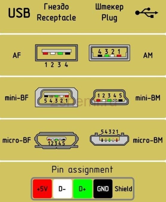
Since the connectors of the first versions of the universal serial bus are not physically different, it is enough to know the wiring of the latest standard. The first contact is supplied with 5 V power, and the 2nd and 3rd wires are used to transmit the signal. Pinout USB cable The colors look like this:
- 1 - red.
- 2 - white.
- 3 - green.
- 4 - black.
USB 3.0 connector pinout
IN latest version standard, instead of 4 contacts, 9 are used. The color scheme of the wiring is shown in the figure and looks like this:
- The assignment of pins 1 to 4 is similar previous version.
- Wires 5−6 and 8−9 are used respectively for transmitting/receiving data via the Super Speed protocol.
- 7 - mass of signal wires.
Type B connectors version 3.0 are not compatible with previous standards.
The pinout of mini-USB is similar to micro, but in the third version of the interface only the latter type of connector is used. Micro-USB 2.0 has 5 contacts, however, only 4 are used. In the latest version, the number of wires has been doubled. Contacts 1-5 perform the same functions as in the connectors of the previous standard, and the rest are designed to solve the following tasks:
- 6−7 and 9−10 - respectively for transmitting/receiving data via a high-speed protocol.
- 8 - ground of information wires.
Micro USB pinout for charging
Although all mobile gadgets charge via USB, there is no single standard, and each manufacturer has developed its own scheme. You can use any power adapter to recharge the battery. For example, in an iPhone, for this you need to connect pins 2, 3 to 4 using a resistor with a nominal resistance of 50 kOhm, and from 5 to 75 kOhm. The main competitor Samsung Galaxy The pinout of the micro-USB charging connector is simpler. You will need to place a jumper between pins 2 and 3, and connect 4 to 5 with a 200 kOhm resistor.
The USB interface began to be widely used about 20 years ago, to be precise, since the spring of 1997. It was then that the universal serial bus was implemented in hardware in many motherboards personal computers. Currently, this type of connecting peripherals to a PC is a standard, versions have been released that have significantly increased the data exchange speed, and new types of connectors have appeared. Let's try to understand the specifications, pinouts and other features of USB.
What are the advantages of Universal Serial Bus?
Implementation this method connections made it possible:
- Quickly connect various peripheral devices to your PC, from the keyboard to external disk drives.
- Make full use of Plug&Play technology, which simplifies the connection and configuration of peripherals.
- Rejection of a number of outdated interfaces, which had a positive impact on functionality computing systems.
- The bus allows not only to transfer data, but also to supply power to connected devices, with a load current limit of 0.5 and 0.9 A for the old and new generations. This made it possible to use USB to charge phones, as well as connect various gadgets (mini fans, lights, etc.).
- It has become possible to manufacture mobile controllers, for example, USB network card RJ-45, electronic keys to log in and log out
Types of USB connectors - main differences and features
There are three specifications (versions) of this type connections that are partially compatible with each other:
- The very first version that has become widespread is v 1. It is an improved modification of the previous version (1.0), which practically did not leave the prototype phase due to serious errors in the data transfer protocol. This specification has the following characteristics:
- Dual-mode data transfer at high and low speed (12.0 and 1.50 Mbps, respectively).
- Possibility of connecting more than a hundred various devices(including hubs).
- The maximum cord length is 3.0 and 5.0 m for high and low transfer speeds, respectively.
- The rated bus voltage is 5.0 V, the permissible load current of the connected equipment is 0.5 A.
Today this standard is practically not used due to its low throughput.
- The dominant second specification today... This standard is fully compatible with the previous modification. A distinctive feature is the presence of a high-speed data exchange protocol (up to 480.0 Mbit per second).
Thanks to full hardware compatibility with the younger version, peripheral devices this standard can be connected to the previous modification. True, the throughput will decrease up to 35-40 times, and in some cases more.
Since these versions are fully compatible, their cables and connectors are identical.
Please note that, despite the throughput specified in the specification, real speed data exchange in the second generation is slightly lower (about 30-35 MB per second). This is due to the implementation of the protocol, which leads to delays between data packets. Since modern drives have a read speed four times higher than the throughput of the second modification, that is, it does not meet current requirements.
- The 3rd generation universal bus was developed specifically to solve problems of insufficient bandwidth. According to the specification, this modification is capable of exchanging information at a speed of 5.0 Gbit per second, which is almost three times the reading speed of modern drives. Plugs and sockets of the latest modification are usually marked blue to facilitate identification of belonging to this specification.

Another feature of the third generation is an increase in the rated current to 0.9 A, which allows you to power a number of devices and eliminate the need for separate power supplies for them.
As for compatibility with the previous version, it is partially implemented; this will be discussed in detail below.
Classification and pinout
Connectors are usually classified by type, there are only two of them:

Note that such convectors are compatible only between earlier modifications.

In addition, there are port extenders of this interface. At one end there is a type A plug, and at the other there is a socket for it, that is, in fact, a “female” - “male” connection. Such cords can be very useful, for example, to connect a flash drive without crawling under the table to the system unit.

Now let's look at how contacts are wired for each of the types listed above.
USB 2.0 connector pinout (types A and B)
Since the physical plugs and sockets of early versions 1.1 and 2.0 do not differ from each other, we will present the wiring of the latter.
 Figure 6. Wiring the plug and socket of type A connector
 Designation:
- A – nest.
- B – plug.
- 1 – power supply +5.0 V.
- 2 and 3 signal wires.
- 4 – mass.
In the figure, the coloring of the contacts is shown according to the colors of the wire, and corresponds to the accepted specification.
Now let's look at the wiring of the classic socket B.

Designation:
- A – plug connected to the socket on peripheral devices.
- B – socket on a peripheral device.
- 1 – power contact (+5 V).
- 2 and 3 – signal contacts.
- 4 – ground wire contact.
The colors of the contacts correspond to the accepted colors of the wires in the cord.
USB 3.0 pinout (types A and B)
In the third generation, peripheral devices are connected via 10 (9 if there is no shielding braid) wires; accordingly, the number of contacts is also increased. But they are located in such a way that it is possible to connect devices of earlier generations. That is, the +5.0 V contacts, GND, D+ and D-, are located in the same way as in the previous version. The wiring for Type A socket is shown in the figure below.
 Figure 8. Pinout of Type A connector in USB 3.0
 Designation:
- A – plug.
- B – nest.
- 1, 2, 3, 4 – connectors fully correspond to the pinout of the plug for version 2.0 (see B in Fig. 6), the colors of the wires also match.
- 5 (SS_TX-) and 6 (SS_TX+) connectors for data transmission wires via the SUPER_SPEED protocol.
- 7 – ground (GND) for signal wires.
- 8 (SS_RX-) and 9 (SS_RX+) connectors for data receiving wires using the SUPER_SPEED protocol.
The colors in the figure correspond to those generally accepted for this standard.
As mentioned above in the nest of this port You can insert a plug from an earlier model, and accordingly, the throughput will decrease. As for the plug of the third generation of the universal bus, it is impossible to insert it into the sockets of the early release.
Now let's look at the pinout for the type B socket. Unlike the previous type, such a socket is incompatible with any plug of earlier versions.

Designations:
A and B are plug and socket, respectively.
Digital signatures for contacts correspond to the description in Figure 8.
The color is as close as possible to the color markings of the wires in the cord.
Micro USB connector pinout
To begin with, we present the wiring for this specification.

As can be seen from the figure, this is a 5 pin connection; both the plug (A) and socket (B) have four contacts. Their purpose and digital and color designation correspond to the accepted standard, which was given above.
Description of the micro USB connector for version 3.0.
For of this connection A characteristically shaped 10 pin connector is used. In fact, it consists of two parts of 5 pins each, and one of them fully corresponds to the previous version of the interface. This implementation is somewhat confusing, especially considering the incompatibility of these types. Probably, the developers planned to make it possible to work with connectors of earlier modifications, but subsequently abandoned this idea or have not yet implemented it.

The figure shows the pinout of the plug (A) and appearance sockets (B) micro USB.
Contacts 1 to 5 fully correspond to the second generation micro connector, the purpose of the other contacts is as follows:
- 6 and 7 – data transmission via high-speed protocol (SS_TX- and SS_TX+, respectively).
- 8 – mass for high-speed information channels.
- 9 and 10 – data reception via high-speed protocol (SS_RX- and SS_RX+, respectively).
Mini USB pinout
This connection option is used only in early versions of the interface; in the third generation this type is not used.

As you can see, the wiring of the plug and socket is almost identical to micro USB, respectively, color scheme wires and contact numbers also match. Actually, the differences are only in shape and size.
In this article we have presented only standard types of connections; many manufacturers of digital equipment practice introducing their own standards; there you can find connectors for 7 pin, 8 pin, etc. This introduces certain difficulties, especially when the question arises of finding a charger for mobile phone. It should also be noted that manufacturers of such “exclusive” products are in no hurry to tell how the USB pinout is done in such contactors. But, as a rule, this information is easy to find on thematic forums.
Correct pinout of the plug and socket of the Micro-USB connector for connecting power and charging a mobile phone or tablet.
Pinout diagram

Assignment of micro-USB connector contacts - socket and plug
USB (Universal Serial Bus) connector is a universal-purpose serial bus, the most common wired connection method external devices to the computer. This connector allows you to organize data exchange between a computer and a video camera, card reader, MP3 player, external hard drive, smartphone.
Charging the battery via Micro USB
In addition, it supplies a 5-volt power supply to charge the battery of wearable gadgets. Since almost all modern lithium batteries have an operating voltage of 3.7 V, then the 5 V supplied via Micro-USB are excellent for replenishing energy. True, not directly to the battery, but through the charger converter.

I’m glad that the connector pinout is the same for all smartphone manufacturers - Samsung, LG, Huaway and others. Thus, a 220 V charger-adapter from one phone is most often suitable for charging another without changing the pinout.
- The main advantage of the Micro-USB connector over other types is the ability to connect Plug&Play devices without the need to restart the computer or manual installation drivers. Devices can be connected while the computer is running and disconnected without having to press any buttons.
Difference between Micro-USB A and B
Please note: The micro connector contains 5 pins. Type B connectors do not use the fourth pin. In type “A” connectors, the fourth contact is connected to GND (minus). And for GND - the fifth contact.
USB (Universal Serial Bus) – Transfer Interface USB data Today it is widespread, used in almost all devices: phones, PCs, MFPs, tape recorders and other devices used both for data transfer and for charging phone batteries.
Types of USB connectors.
Exists a large number of varieties of USB connector types. All of them are shown below.
Type A- active, power supply device (computer, host). Type B- passive, connected device (printer, scanner)
USB cable pinout by color.
USB 2.0 pinout.

USB is a serial bus. It uses 4 shielded wires: two for power (+5v & GND) and two for differential data signals (labeled D+ and D-).

USB micro
USB micro has been used since 2011 in phones, MP3 and other devices. Micro is a newer variation of the mini connector. It has the advantage of connecting connectors, the connector is connected tightly to the plug and provides a tight connection.
Universal Serial Bus (USB) wiring diagram
USB connector wiring diagram
USB connector wiring diagram (cable and device)

USB connector wiring diagram (cable and device)
USB signals are transmitted over two wires (twisted pair) of a shielded four-core cable.
VBUS – voltage +5 Volts of the power circuit, GND – contact for connecting the “housing” of the power circuit. The maximum current consumed by the device through the USB bus power lines should not exceed 500 mA. Data is transmitted through the D- and D+ pins of the USB connector. Differential data transfer method is the main one for USB.
USB cable connectors
For the USB cable, special USB connectors are used. The USB cable is directional, so for correct connection, USB connectors have different configurations. There are two types of USB connectors: Type A (see Fig. 7. and Fig. 8.) and Type B (see Fig. 9., Fig. 10. and Fig. 11).

Fig.7. Regular USB cable connector Type A
In accordance with the 1.0 specification, USB Type A connectors are used for connection “to the host”, i.e. installed on the controller or USB hub side.

Fig.8. “Proprietary” USB cable connector Type A
In accordance with the 1.0 specification, USB Type B connectors are used for connection “to the device”, i.e. for connecting peripheral devices.

Fig.9. Regular USB cable connector Type B. This connector is suitable for, for example,
to connect a printer

Fig. 10. Regular USB connector mini cable Type B

Fig. 11. Micro USB cable connector Type B. In the figure, below the USB symbol, the Type B designation is clearly visible
In Fig.12. and Fig.13. USB cables shown. These USB cables are equipped with standard USB connector cable Type A and USB mini connector of cable Type B.

Fig. 12. USB cables are equipped with a regular Type A USB cable connector (in the picture on the left) and a Type B USB mini cable connector (in the picture on the right). Type B is designated as B

Fig. 13. USB cables are equipped with a regular Type A USB cable connector (in the picture on the left) and a Type B USB mini cable connector (in the picture on the right). Type B is designated as b

Fig. 14. USB cable equipped with a miniature connector called micro USB
USB supports hot (power on) plugging and unplugging of devices. This is achieved by increasing the length of the grounding contact of the connector in relation to the signal contacts, see Fig. 15. When a USB connector is connected, the grounding contacts are closed first, the potentials of the bodies of the two devices are equalized, and further connection of the signal conductors does not lead to overvoltages, even if the devices are powered from different phases of a three-phase power network.

Fig. 15. The length of the grounding contact (in the figure, pin 4 GND at the top) of the connector is increased in relation to the signal (in the figure, pin 3 D+ at the bottom) contacts. The upper contact is longer than the lower one. This allows you to connect and disconnect devices without turning off the power (so-called “hot plugging and unplugging”)

Fig.15.a. Power pin length USB connector flash cards (outer contacts in the figure) are enlarged in relation to the signal contacts (middle contacts in the figure). This allows you to connect and disconnect devices without turning off the power (so-called “hot plugging and unplugging”)
The mating parts of the USB connectors are located on peripheral devices connected via USB, see Fig. 16. and Fig.17.

Fig. 16. USB cable connector. The USB symbol is clearly visible

Fig. 17. USB mini Type B cable connector

Fig. 18. Comparison of USB connector sizes. A regular USB cable connector Type A (in the picture on the left), a USB mini cable connector Type B (in the picture in the center) and a USB micro cable connector Type B (in the picture on the right). Type B is designated as B


