How to make a quadcopter based on arduino. How to make a quadcopter based on arduino Flight controller on arduino
Hello hackers!
In this series of articles, we will open the lid of the quadrocopter a little more than the hobby requires, and also write, configure and launch our own program for the flight controller, which will be a regular Arduino Mega 2560 board.
We have ahead:
- Basic concepts (for beginner quad pilots).
- PID controllers with an interactive web-demonstration of work on a virtual quadcopter.
- Actually a program for Arduino and a tuning program for Qt.
- Dangerous tests of a quadrocopter on a rope. First flights.
- Crash and loss in the field. Automatic search from the air using Qt and OpenCV.
- Final successful tests. Summarizing. Where to go?
The material is voluminous, but I will try to keep within 2-3 articles.
Today we are waiting for: a spoiler with a video of how our quadcopter flew; basic concepts; PID controllers and the practice of selecting their coefficients.
Why all this?
Academic interest, which, by the way, pursues not only me (,). And, of course, for the soul. I got great pleasure while working and felt real indescribable happiness when "THIS" flew with my program 🙂
For whom?
This material may be of interest, among other things, to people who are far away, or are just going to work on multi-rotor systems. Now let's talk about the purpose of the main components of a quadrocopter, about how they interact with each other, about the basic concepts and about the principles of flight. Of course, all the knowledge that we need can be found on the net, but you can’t force them to look for them on the vast Internet.
Without prejudice to understanding in basic terms, feel free to skip everything you know until the next unfamiliar term, bold, or to an incomprehensible illustration.
NO #1!
Do not undertake to write your own program for the flight controller until you try ready-made solutions, which are now quite a lot (Ardupilot, MegapirateNG, MiltiWii, AeroQuad, etc.). First, it's dangerous! It takes practice to control a quadcopter without GPS and a barometer, and even more so when it bugs, rolls over, flies not quite where it should be - and this is almost unavoidable during the first tests. Secondly, it will be much easier for you to program by understanding what needs to be programmed and how it should work in the end. Believe: flight math is just a small part of the program code.
NO #2!
Do not undertake to write your own program for the flight controller if you are not pursued by an academic interest and you only need what ready-made solutions have been able to do for a long time (fly, take pictures, shoot video, fly on a mission, etc.) While you write everything yourself, a lot of time will pass, even if you are not alone.
Basic concepts
Quadcopters are different, but all of them are united by four rotors:
Despite the apparent symmetry, it is very important for the pilot to distinguish where the quadcopter has the front (shown by the arrow). Here, like radio controlled models cars: when the “forward” command is given, the quadcopter flies not where the pilot is looking, but where the imaginary nose of the quadcopter is pointing. This is fraught with danger: it can be difficult for beginners to return to themselves a wind-blown craft deployed somehow sideways (of course, we are not talking about flying on the camera in the first person and about “smart” flight modes using a compass and GPS.) this problem can be partly helped by front propellers or beams of a different color, some kind of ball in front or multi-colored LEDs. But all this turns out to be useless when the pepelats rapidly turns into a point above the horizon.
We will be flying on an “X” shaped quadcopter frame because I like the look of it better. Each design has its own advantages and purpose. In addition to quadcopters, there are other multicopters. Even if you do not count exotic options, there are still a whole bunch of their types! 
Let's figure out how our quadrocopter is arranged inside, and what should the flight controller, which we plan to program, do. 
corners pitch, roll and yaw (pitch, roll, yaw)- angles used to determine and set the orientation of the quadcopter in space. 


Sometimes the word "angle" is omitted and they simply say: pitch, roll, yaw. But according to Wikipedia, this is not entirely accurate. The flight of the quadcopter in the desired direction is achieved by changing these three angles. For example, in order to fly forward, the quadcopter must tilt due to the fact that the rear motors spin a little more than the front ones: 
Quadcopter gas- arithmetic mean between the speeds of rotation of all motors. The more gas, the greater the total thrust of the motors, the more they drag the quadcopter up(DO NOT FORWARD!!! "Sneakers on the floor" here means the fastest rise). Usually measured as a percentage: 0% - the motors are stopped, 100% - they rotate at maximum speed. hover gas- the minimum throttle level required to keep the quadcopter from losing altitude.
Throttle, pitch, roll, yaw - if you can control these four parameters, then you can control the quadcopter. They are also sometimes called control channels. If you have purchased a dual-channel remote control, you will not be able to cope with the quadcopter. Three-channel is more suitable for small helicopters: you can fly without roll control, but it’s not convenient on a quadcopter. If you want to change flight modes, you'll have to shell out for a five-channel remote. If you want to control the tilt and pan of the camera on board, two more channels are a plus, although professionals use a separate remote control for this.
There are many flight modes. Used and GPS, and a barometer, and a rangefinder. But we want to implement the basic - stabilization mode ( stab, stabilizer, fly in a "stub"), in which the quadcopter keeps those angles that are set to it from the remote control, regardless of external factors. In this mode, in the absence of wind, the quadcopter can hover almost in place. The wind will have to compensate the pilot.
The direction of rotation of the screws is not chosen by chance. If all the motors rotated in one direction, the quadcopter would rotate in the opposite direction due to the moments created. Therefore, one pair of opposing motors always rotates in one direction, and the other pair in the other. The effect of the occurrence of moments of rotation is used to change the yaw angle: one pair of motors starts to rotate a little faster than the other, and now the quadcopter slowly turns to face us (what a horror): 

- LFW - left front clockwise rotation (left front, clockwise rotation)
- RFC - right front counter clockwise rotation (right front, counterclockwise rotation)
- LBC - left back counter clockwise rotation (left back, counterclockwise rotation)
- RBW - right back clockwise rotation (right rear, clockwise rotation)
The rotation speed of the motors is controlled flight controller (controller, brains). Usually this is a small board or box with many inputs and outputs. There are a huge number of different controllers with a different set of features, different firmware, different tasks. Here are just a few: 
The generalized task of the flight controller is to perform a control cycle several tens of times per second, which includes: reading sensor readings, reading control channels, processing information and issuing control signals to the motors in order to fulfill the pilot's commands. This is what we are going to program.
There are a lot of different types of sensors that can be used. We will use the already almost mandatory in all quadrocopters three-axis gyroscope and three-axis accelerometer. Accelerometer measures acceleration, gyroscope measures angular velocity. Thanks to them, the flight controller learns the current pitch, roll and yaw angles. These sensors are built into the flight controller, and are external. The process of calculating three angles according to the readings of the sensors is a topic for a separate article. But we do not need to know this here: the MPU-6050 will do everything for us. This is a small board that performs the necessary calculations and filtering within itself and issues almost ready-made corners using the i2c protocol. It remains for us to count them, process them with the rest of the data and issue control signals to the motors.
Motors on multicopters consume high currents, so the flight controller does not control them directly, but through special hardware drivers called speed controllers (ESC, regulator, eska). These regulators are powered by the main onboard battery, they receive a control signal from the controller, and at the output they have three wires (A, B, C) that go directly to the motors (each motor has its own regulator!) 
The "protocol" of communication between the controller and the motor is not as important to us as the "protocol" of communication between the flight controller and the controller, because we have to programmatically control the controller from the controller. There are regulators controlled by i2c, but the most common are controlled by a square wave signal with a minimum of 0 volts and a maximum of 3-5 volts (it is called PWM or PWM, and some argue that it is more correct - PPM. More details, for example).
“Protocol” is a big word: in order to command the motor to rotate at maximum speed, the controller must send pulses lasting 2 milliseconds, interspersed with a logical zero lasting 10 - 20 milliseconds. An impulse duration of 1 millisecond corresponds to stopping the motor, 1.1 ms - 10% of the maximum speed, 1.2 ms - 20%, etc. In practice, the duration of zero does not play any role, only the duration of the pulse itself is important.
For all its seeming simplicity, here lies an ambush: flight controllers are different from different settings, regulators are different, and the minimum (1 ms) and maximum (2 ms) are not universal. Depending on a variety of factors, the 1-2ms range could actually be 1.1 - 1.9ms. In order for the regulator and controller to speak exactly the same language, there is a procedure regulator calibration. During this procedure, the ranges of the regulators are changed and become equal to the range of the controller. The procedure is hardwired into the program of each controller and includes several simple steps(steps may vary depending on the manufacturer - read the instructions!):
- Turn off power to the controller.
- Remove the propeller from the motor.
- Apply a signal corresponding to the maximum rotation speed to the controller input.
- Apply power to the regulator. The motor must remain stationary without assistance.
- Apply a signal corresponding to the minimum rotation speed to the input of the regulator.
- Pause for 1-2 seconds, wait for a characteristic squeak.
- Turn off power to the controller.
After that, the corresponding interval boundaries will be entered into the controller. When trying to take off with uncalibrated controls, the consequences can be unexpected: from a sudden dash of a quadcopter into the nearest tree, to complete immobility of the motors at any throttle setting.
PWM with exactly the same principle uses and onboard receiver. it small device, which receives radio control signals from the ground and transmits them to the flight controller. Most often, the flight controller has its own input for each control channel (gas, pitch, roll, etc.), which receives PWM. The logic of interaction is simple: a command, for example, "70% gas" continuously goes from the ground to the receiver, where it is converted to PWM and sent to the flight controller via a separate wire. Similarly with pitch, roll, yaw.
Since there are friendly PWM relations between the receiver and the controller, they will also have to be calibrated: remotes with receivers are different with their own operating ranges. The controller must be able to adapt. procedure radio calibration, unlike the calibration of the regulators, we will have to create it ourselves as part of the flight program. The general calibration plan is as follows:
- Remove the propellers from the motors just in case.
- Somehow put the controller into radio calibration mode.
- The controller starts the radio calibration for several tens of seconds.
- In the allotted time, we move all the sticks of the remote control in all directions until they stop.
- The controller remembers the highs and lows for all control channels during internal memory for centuries.
So: during radio calibration, the flight controller remembers the receiver ranges for all control channels; during the calibration of the controls, the range of the flight controller is written to all controls.
In addition to the program for the flight controller, one more program is needed: flight controller setup interface. Most often, this is a PC program that connects to the flight controller via USB and allows the user to set up and check the flight program, for example: run radio calibration, adjust stabilization parameters, check the operation of sensors, set the flight path on the map, determine the behavior of the multicopter in case of signal loss and much more. We will write our configuration interface in C++ and Qt as a console utility. Here it is, looking ahead: 
Nobody is immune from accidents. Even ten inch plastic screws on small motors can leave bloody bruises on the skin that will hurt for another week (personally verified). It's easy to get yourself a new make-up and hairstyle if you hook the throttle stick on the remote control while you carry the included quadrocopter. Therefore, the flight controller must provide at least some security: the mechanism armed/disarmed. The “disarmed” state of the quadcopter means that the motors are disabled and even a full throttle command from the remote control has no effect, although power is applied. The “armed” state of the quadcopter means that commands from the remote control are carried out by the flight controller. In this state, quadcopters take off, fly and land. The quadcopter turns on and should immediately enter the disarmed state in case an inattentive pilot turns it on when the throttle stick on the remote is not at zero. In order to put the copter into the “armed” state, the pilot needs to make some kind of predetermined gesture with the remote control sticks. Often this gesture is to hold the left stick in the lower right corner (throttle = 0%, yaw = 100%) for a couple of seconds. After that, the flight controller does at least a minimal self-test and, if it passes successfully, " arming” (ready to fly!) Another gesture (throttle = 0%, yaw = 0%) quadcopter “ disarmed". Another good security measure is autodisarm, if the gas was at zero for 2-3 seconds.
About motors, batteries, regulators, propellers
Stabilization Mathematics, PID Controllers (PID)
If you decide to get into multicopters, then sooner or later you will have to deal with PID control tuning, since this mathematical apparatus is used in almost all stabilization tasks: stabilization of quadcopter angles in the air, GPS flight and position holding, barometer altitude hold, brushless mechanisms stabilization of the video camera in flight (camera suspension).
You buy a two-axis gimbal for the camera, put, for example, a GoPro there, turn it on and instead of stabilization you get convulsions, vibrations and jerks, although all sensors are calibrated and mechanical problems are eliminated. The reason is incorrect parameters of the PID controllers.
You assemble a multicopter, calibrate sensors, regulators, radio, check everything, try to take off, and it is so dull in the air that even a light breeze turns it over. Or vice versa: he is so sharp that he suddenly takes off and twists a triple somersault without permission. The reason is the same: PID controller parameters.
For many devices using PID controllers, there are tuning instructions, or even several, in addition to numerous video instructions from the users themselves. But to make it easier to navigate in this variety, it is useful to understand how these regulators are arranged inside. In addition, we are going to write our own quadcopter stabilization system! I propose, together with me, to “reinvent” and "on the fingers" to understand PID controller formula. For those who prefer dry mathematical language, I recommend Wikipedia, because in Russian, the material is not so detailed yet.
We will consider a quadcopter in a two-dimensional space, where it has only one angle - the roll angle, and two motors: left and right. 
The flight controller continuously receives commands from the ground: "roll 30 degrees", "roll -10 degrees", "roll 0 degrees (keep horizon)"; its task is to perform them as quickly and accurately as possible with the help of motors, taking into account: wind, uneven distribution of the weight of the quadcopter, uneven wear of the motors, inertia of the quadcopter, etc. Thus, the flight controller must continuously decide what rotation speed to apply to each motor, taking into account the current value of the bank angle and the required one. Continuous is, of course, a strong word. It all depends on the computing capabilities of a particular hardware. On Adruino, it is quite possible to fit one iteration of the processing and control cycle into 10 milliseconds. This means that once every 10 milliseconds, the angles of the quadcopter will be read, and based on them, control signals will be sent to the motors. These 10 milliseconds are called regulation period. It is clear that the smaller it is, the more often and more accurately the regulation takes place.
The gas level comes from the receiver to the controller. Let's designate it. Let me remind you that this is the arithmetic average between the rotation speeds of all motors, expressed as a percentage of the maximum rotation speed. If and are the rotation speeds of the left and right motors, then:
where is the reaction of the quadcopter (force), which creates a torque due to the fact that the left motor rotates faster than the gas, and the right motor rotates the same amount more slowly. can also take negative values, then the right motor will spin faster. If we learn how to calculate this value at each iteration of the processing loop, then we can control the quadcopter. It is clear that at least it should depend on the current bank angle () and the desired bank angle (), which comes from the control panel.
Let's imagine the situation: the command "keep the horizon" ( = 0) is received, and the quadcopter has a roll to the left: 
- difference (error) between and , which the controller seeks to minimize.
The greater the difference between the desired bank angle and the current one, the stronger the reaction should be, the faster the left motor should spin relative to the right one. If this is written using our notation:
Here P is the coefficient of proportionality. The larger it is, the stronger the reaction will be, the sharper the quadrocopter will react to deviation from the required bank angle. This intuitive and simple formula describes the work proportional controller. The essence is elementary: the stronger the quadcopter deviated from the required position, the harder you need to try to return it. Unfortunately, this formula will have to be complicated. The main reason is overshoot.
In a few tens of milliseconds (several iterations of the processing cycle), under the influence of a proportional controller, the quadcopter will return to the required (in this case, horizontal) position. All this time, the error and the effort will have the same sign, although they will become less and less in absolute value. Having gained some turning speed (angular speed), the quadcopter will simply roll over to the other side, because no one will stop it in the required position. It's like a spring that always wants to return to its original position, but if you pull it back and release it, it will oscillate until friction takes over. Of course, friction will also act on the quadrocopter, but practice shows that it is not enough.
For this reason, one more term must be added to the proportional controller, which will slow down the rotation of the quadcopter and prevent overshoot (rolling over in the opposite direction) - a kind of imitation of friction in a viscous medium: the faster the quadcopter turns, the harder you need to try to stop it, of course, in reasonable limits. Rotation speed (rate of error change) will be denoted as , then:
where D is an adjustable coefficient: the larger it is, the stronger the stopping force. From a school course in physics, vague memories emerge that the rate of change of any quantity is the derivative of this quantity with respect to time: ![]() .
.
And now the proportional controller turns into a proportional-differential (proportional term and differential):
.
The error is easy to calculate, because at each iteration we know and ; P and D - configurable parameters before launch. To calculate the derivative (rate of change), it is necessary to store the previous value, know the current value and know the time that has elapsed between measurements (regulation period). And here it is - sixth grade school physics (velocity = distance / time):
.
- regulation period; - error value from the previous iteration of the regulation cycle. By the way, this formula is simplest way numerical differentiation, and it will suit us here quite well.
Now we have a proportional-derivative regulator in a flat "bicopter", but there is one more problem. Let the left edge weigh a little more than the right, or, equivalently, the left motor works a little worse than the right. The quadcopter is slightly tilted to the left and does not turn back: the differential term is zero, and the proportional term, although it takes a positive value, is not enough to return the quadcopter to a horizontal position, because the left edge weighs a little more than the right one. As a result, the quadcopter will pull to the left all the time.
A mechanism is needed to monitor such deviations and correct them. A characteristic feature of such errors is that they show themselves over time. The integral term comes to the rescue. It stores the sum of all errors over all iterations of the processing loop. How will this help? If the proportional term is not enough to correct a small error, but it still exists - gradually, over time, the integral term gains strength, increasing the reaction and the quadcopter takes the required roll angle.
There is a nuance here. Suppose it is equal to 1 degree, the regulation cycle is 0.1s. Then in one second the sum of the errors will take the value of 10 degrees. And if the processing cycle is 0.01s, then the sum will gain as much as 100 degrees. In order for the integral term to gain the same value at different regulation periods in the same time, the resulting amount will be multiplied by the regulation period itself. It is easy to calculate that in both cases the sum of 1 degree is obtained from the example. Here it is - the integral term (so far without an adjustable coefficient):
.
This formula is nothing more than a numerical time integral of a function in the range from zero to the current moment. That is why the term is called integral: ![]() ,
,
where T is the current moment in time.
It's time to write down the final formula for the proportional-integral-derivative controller:
,
where is one of the adjustable parameters, which are now three: . This formula is convenient to apply from code, but here is the formula that is given in textbooks:
.
There are several variations of it, for example, you can limit the modulus of the integral term so that it does not exceed a certain allowable threshold (we will do so).
Practice
Well, now it's time to practice the selection of coefficients. Readers are offered a JavaScript page with a virtual quadcopter, which they have already seen in the pictures: selection of PID controller parameters for a quadrocopter(JSFiddle). At the first start, overshoot is immediately visible - fluctuations around the required position. When the oscillation stops, you can observe the effect that the proportional gain cannot cope with the error due to the "asymmetric" quadcopter (set by the "Asymmetry" checkbox). Parameters P, I, D are available for customization. Now you know what to do with them. "Scrolling" under the quadcopter can control the required roll value. "Interval (ms):" - regulation interval. Reducing it is "cheating", but seeing how it affects the quality of stabilization is very useful.
For lovers of "pure" mathematics, we can offer set up an abstract PID controller
The entered parameters are not automatically applied: you need to click "Apply". A couple of small tips: if you feel that the quadcopter is too slow to respond to control, you can increase P, but too large a value of P can lead to overshoot. Overshoot will be dealt with by setting D, but values that are too high will result in frequent fluctuations, or overshoot again. The I parameter is usually 10 - 100 times smaller than the P parameter, since its strength is in accumulation over time, not in rapid response.
Manual tuning of PID parameters takes practice. There are analytical methods for calculating them, but they require good training and accurate knowledge of many parameters of a particular custom system. As an intermediate between manual selection and analytical calculation, there is a wide range of empirical methods proposed by various researchers.
In our 2D quadcopter, only one angle changes - the roll angle. A tuning 3D quadcopter will require three independent PID controllers for each of the angles, and the control of a particular motor will represent the sum of the efforts on all controllers.
Conclusion of the first part
In this article, we got acquainted with the basic concepts: quadcopter and the principle of flight, pitch, roll, yaw, gas, hovering gas, stabilize flight mode, flight controller, gyroscope, accelerometer, speed controller, PWM, regulator calibration, radio calibration, on-board receiver, flight controller settings interface, armed/disarmed status, autodisarm .
After that, we reinvented the formula PID controller touching a little numerical differentiation and integration, and experienced the hard way how to adjust the settings P, I, D on the virtual quadcopter .
Now, if you're good at lightsaber programming, you can start your own quadcopter stabilization program, or better yet, join existing open source projects with fresh ideas. Well, in a week or two I will continue the story of how it was all programmed, tested, fell, cut my fingers and completely flew off in an unknown direction.
In conclusion of this part, I simply have to mention the person who helped me in choosing components and setting up the most complex (first!) quadcopter on MegapirateNG firmware and patiently answered hundreds of questions on these very basic concepts: SovGVD, thank you! 🙂
As a reward for those who were able to squander this whole sheet, I post the promised small video, how our quadcopter with our “invented” PID controllers flies on our Arduino Mega 2560 program:
Of course, it lacks GPS, as in commercial and mass products, it lacks stability a bit, but it is OURS, and we know it inside and out to the last multiplier with the integral coefficient! And it's really cool that such technologies are available to us today.
ATTENTION, the article is outdated, but it can still be used for informational purposes
As promised, as soon as I fly, I will write a full-fledged post about the assembly of my flying unit. Surely, many have long looked at how an “ordinary” office employee collects it in 2 hours, I’ll immediately note that I’m not an “ordinary” office worker, so I’m not a very good pilot yet, but it’s important that the quadcopter flies and responds adequately to control. First and foremost - if you decide to collect, do not save money and do not think that you are smarter than those who already fly, just keep in mind that theory is somewhat at odds with practice.
There are a large number of firmware, ready-made controllers, sensor options, motors, etc. etc. - there are plenty to choose from, but in the article I will focus on only one option based on Arduino Mega, MegaPirate firmware and relatively cheap sensors.
Result
In order not to torment you, %username%, this is how it flies without special settings, calibrations and balancing in inept hands:And now what do we need for this ...
Continuation
PS: I hope people in the RC thread will forgive me for inaccuracies and correct me where necessary.
In this article we will talk about arduino quadcopters, their advantages and price categories.
Quadrocopter with the functions of a computer device.

AT modern world There is a wide variety of quadcopter models that are designed to be used for a variety of purposes. They are not just toys, which they were perceived from the very beginning of their appearance on the domestic market. Now they are devices designed to perform a wide variety of tasks. They are used in many cases for professional creative activities. In order for the quadcopter to work properly, it must be equipped with additional parts in addition to the base at the factory. In order for the device to be controlled by the remote control remote control it is necessary to install a processor and many other parts of the electronics system on it. Presented today a large number of processors that are used to create high-quality and functional quadrocopters. Among them, Arduino stands out. It is a powerful enough processor that allows the quadcopter to have some of the functions of a computer device.

Today, an arduino quadcopter can be easily purchased at any online store that specializes in the production of such devices. Thanks to given processor the largest and most powerful devices in terms of technical parameters are created. They are suitable for a wide variety of tasks. They are designed for both ordinary flights and professional filming. Thanks to a powerful processor, they easily perform all the tasks set by users. The speed of communication with the remote control is greatly increased. In addition, real-time videos are instantly transmitted to mobile devices, which are connected to the quadcopter on this moment. It should be noted that many users assemble devices on the Arduino processor on their own. It is available in almost every specialty store.
Features of a quadcopter on Adruino.

Arduino devices are very popular because they are very convenient to use. Quadrocopters of this type quickly perform all the tasks set by users. With this processor, it is possible to get a high-quality device that will allow you to enjoy limitless possibilities and during a normal flight, and even during the filming process. Images are obtained from high level permissions. Arduino devices work flawlessly. Thanks to this processor, the device itself is able to carry out its work for a long period of time, and its system will not fail. Devices on latest versions Arduinos are not budget. However, this allows users to get professional-level quadcopters that will quickly and without interruption perform all the tasks set by consumers. It ensures reliable operation of the quadcopter.
The quadcopter is also self-powered. The total cost of such a homemade product is about $ 60.
If there is a more substantial amount, then it is more promising to equip the homemade with brushless motors with the appropriate controllers.
A gyroscope and an accelerometer are used to stabilize the flight. The gyroscope is needed in order to determine the angle of inclination of the quadrocopter relative to the earth's gravity. The accelerometer is needed in order to calculate the acceleration.
Materials and tools:
- lithium batteries(at 3.7 V);
- wires;
- transistor ULN2003A Darlington Transistor (more powerful transistors can be used);
- motors type 0820 Coreless Motors;
- Arduino Uno microcontroller;
- MPU-6050 board (this is both a gyroscope and an accelerometer);
- availability of a 3D printer or access to it;
- necessary tools.
Manufacturing process:
Step one. Building a quadcopter body
The body is made very quickly and simply. It is printed using a 3D printer. Creating a frame in this way is good because it comes out easy, all thanks to the honeycomb printing. The parts were designed using the Solidworks program. With this program, you can edit the parameters of the case, make your own changes to it, if necessary.


After the quadcopter frame is printed, you can install the motors and solder wires to them.


Step two. Connecting the Arduino
How to connect the MPU6050 board can be seen in the diagram below. It is important to understand that the Arduino library implies the connection through these pins. If a circuit from another manufacturer is used, it is important to ensure that the contacts are in the same sequence.

The board only uses 3.3V to power it, if you power it with 5V it will be damaged. Some MPU6050 boards have a fuse that protects the system from high voltage but it's better not to risk it. If the board has an AD0 pin, it must be connected to ground (GND). In this case, the VIO is connected to the AD0 output directly on the board, so you do not need to connect the AD0 pin.


In order for the Arduino to control the motors, transistors are needed, thanks to them it will be possible to apply a large voltage to the motors. You can see in more detail how all the elements are connected in the diagram.
Step three. Sketch for Arduino
After the MPU-6050 is connected to the Arduino, you need to turn it on and upload the I2C scanner code sketch. Next, you need to copy the program code and paste it into an empty sketch. After that, you need to open the Arduino IDE serial monitor (Tools->Serial Monitor) and make sure that the 9600 is connected.
If everything is done correctly, the I2C device will be detected, it will be assigned the address 0x68 or 0x69, it must be written.
Next, a sketch is loaded that processes information from the gyroscope and accelerometer. There are many of them on the Internet, but it is best to use.

The final step is to calibrate the gyroscope and accelerometer values. To do this, you need to find a flat surface and put the MPU6050 on it. Next, the sketch for calibration is launched, the obtained deviation data is recorded and then used in the MPU6050_DMP6 sketch.
Step four. Program for Arduino
thanks to the program that is posted, the quadcopter stabilizes and hangs in a stable state. Further, with the help of this program, the quadrocopter is controlled.

Two PID controllers are used to stabilize the quadcopter. One is for pitch and the other is for roll. The controller measures the rotation speed of the propellers and, based on this, the quadrocopter is controlled.
Step five. Quadcopter modification
The main problem with a small and cheap quadcopter is its weight. To solve this problem, you need to install more powerful and lighter motors, brushless motors are best, they are also called valve motors. They are much better than brush ones, but you also need to buy speed controllers for them, so the cost of homemade products increases dramatically.
Despite the fact that quadrocopters are extremely fashion theme, choosing components to assemble your device is still not so easy. Selecting parts for a particular project is an agonizing search for the optimal combination of weight, power and functionality. So before we plunge into the world of countless online stores and nameless Chinese manufacturers, let's do some preparatory work.
What is a quadrocopter and what is it for
Multirotors, also known as multicopters or simply copters, are unmanned aerial vehicles designed for entertainment, taking photos and videos from the air, or practicing automated systems.
Quadcopters are usually distinguished by the number of motors they use, ranging from a bicopter with two motors (like the GunShip from the Avatar movie) to an octacopter with eight. In fact, the number of motors is only limited by your imagination, budget and flight controller capabilities. The classic version is a quadcopter with four motors located on criss-cross beams. The Frenchman Étienne Oehmichen tried to build such a configuration back in 1920, and in 1922 he even succeeded. In fact, this is the easiest and cheapest option to make an aircraft capable of lifting small cameras like a GoPro without any problems. But if you are going to take off with serious photo and video equipment, then you should choose a copter with a large number of motors - this will not only increase the carrying capacity, but also add reliability if one or more motors fail in flight.
flight theory
In the theory of flight (aerodynamics), it is customary to distinguish three angles (or three axes of rotation) that define the orientation and direction of the aircraft's motion vector. Simply put, the aircraft “looks” somewhere and moves somewhere. Moreover, he can move not where he “looks”. Even airplanes in flight have some kind of “drift” component that takes them away from their heading. And helicopters can generally fly sideways.
These three angles are called roll, pitch and yaw. Roll is the rotation of the vehicle around its longitudinal axis (the axis that runs from nose to tail). Pitch is a turn around its transverse axis (nodding, tail lifting). Yaw - a turn around a vertical axis, most of all similar to a turn in the "ground" sense.
Basic maneuvers (from left to right): straight ahead, roll/pitch and yaw
AT classical scheme helicopter main rotor with the help of a swashplate controls the roll and pitch. Since the main rotor has non-zero air resistance, the helicopter has a torque directed in the direction opposite to the rotation of the rotor, and to compensate for it, the helicopter has a tail rotor. By changing the output of the tail rotor (revs or pitch), a classic helicopter controls its yaw. In our case, everything is more complicated. We have four screws, two of them rotate clockwise, two counter-clockwise. Most configurations use fixed pitch propellers and can only be controlled by their revolutions. If they all spin with the same speed, then they cancel each other: yaw, roll and pitch will be zero.

If we increase the rpm of one clockwise propeller and decrease the rpm of the other clockwise propeller, then we keep the total torque and the yaw will still be zero, but roll or pitch (depending on where we do his “nose”) will change. And if we increase the speed on both propellers that rotate clockwise, and reduce the propellers that rotate counterclockwise (to preserve the total lift), then a torque will arise that will change the angle of yaw. It is clear that we will not do all this ourselves, but the on-board computer, which will receive a signal from the control knobs, add corrections from the accelerometer and gyroscope and turn the screws as it needs. In order to design a quadcopter, it is necessary to find a balance between weight, flight time, engine power and other characteristics. All this depends on the specific tasks. Everyone wants a quadcopter to fly higher, faster and longer, but the average flight time is 10 to 20 minutes depending on battery capacity and total flying weight. It is worth remembering that all characteristics are interconnected and, for example, an increase in battery capacity will lead to an increase in weight and, as a result, to a decrease in flight time. To find out approximately how long your structure will hang in the air and whether it can even get off the ground, there is a good online calculator ecalc.ch. But before you drive data into it, you need to formulate requirements for the future device. Will you install a camera or other equipment on the device? How fast does the machine need to be? How far do you need to fly? Let's look at the characteristics of the various components.
 PX4 - on-board computer with a full UNIX system
 Frame
The main point to decide when choosing a frame is whether you are going to use a pre-made frame or make your own. With a finished frame, everything is easier, and in any case, you will have to order a lot of parts. At the same time, given the prices in Chinese stores, a homemade version may be more expensive. On the other hand, it will be easier to repair your own frame in case of an accident. And, of course, with your own hands you can make any, even the most crazy design. Let's take a closer look at the self-assembly option.
You can make a frame from any improvised materials (wood, aluminum, plastic, and so on). You can get a little more serious and cut it on a CNC machine from woven carbon, and you can complicate the task and make a folding structure.
The easiest option for DIY enthusiasts is to go to OBI, Leroy Merlin or the construction market and buy a 12x12 square aluminum tube and 1.5mm thick aluminum sheet. In order to make a frame from such materials like “four sticks and fasteners”, a drill or a hacksaw is enough. But you need to be prepared for the fact that such a design will not last long. Still, all these profiles are made of very soft material (AD31 / AD33), it will easily bend during flights.
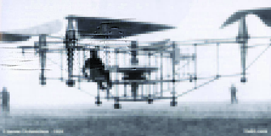 Oehmichen No. 2, manned quadrotor by French engineer Étienne Oehmichen, launched in 1922
 As a sample for your frame, you can take a simplified factory frame or find it on the Internet. finished drawing. More complex materials (for example, carbon fiber) can be replaced with aluminum - if it turns out to be heavier, then not much. In any case, you should pay attention to the length and symmetry of the rays. The length of the beams is selected based on the diameter of the propellers used, so that after their installation, the distance between the circles of the rotating propellers is at least 1–2 cm, and even more so, these circles should not intersect. The motors mounted on the beams should be equidistant from the center of the frame where the “brain” will be located, and (in most cases) be at the same distance from each other, forming an equilateral polygon.
When designing, it is worth considering that the center of the frame must coincide with the center of gravity, so installing the battery at the back between the arms is a bad idea unless it is compensated by a load in the front, such as a camera. Think about what your device will land on, for beginners, you can be advised to adapt something soft on the “belly” or the ends of the rays, for example, dense foam rubber or tennis balls. And also protect the battery in case of a bad landing, for example, place it between the frame plates or place it under high landing skis.
info
Flying in first person view (FPV) is very exciting, especially if you use video goggles and HeadTracker, which will follow the movements of the head on the gimbal of the FPV camera, making it feel like you are in the cockpit.
Motors and propellers
Due to the rotation of the motors in different directions, it is necessary to use multidirectional propellers: forward rotation (counterclockwise) and reverse rotation (clockwise). Two-bladed propellers are commonly used and are easier to balance and find in stores, while three-bladed propellers will give more thrust with a smaller propeller diameter but cause a lot of balancing headaches. A bad (cheap and unbalanced) prop can fall apart in flight or cause strong vibrations that are transmitted to the flight controller's sensors. This will lead to serious stabilization problems and will cause a lot of blur and jelly in the video if you are filming something from the quad or flying in POV.
 speed controller,
 aka ESC
Any propeller has two main parameters: diameter and pitch. They are designated variously: 10 × 4.5, 10 × 45 or simply 1045. This means that the diameter of the propeller is 10 inches, and its pitch is 4.5 inches. The longer the propeller and the larger the pitch, the more thrust it can create, but this will increase the load on the motor and increase the current consumption, as a result, it can overheat and the electronics will fail. Therefore, the screws are selected under the motor. Well, or a motor for screws, here's how to look. Usually on the sites of motor sellers you can find information about the recommended propellers and batteries for the selected motor, as well as tests of the generated thrust and efficiency. There are also variable-pitch propellers, which in theory will increase maneuverability, but in reality will add complex mechanics that tend to wear out and break, followed by expensive repairs.
Also, the larger the screw, the greater its inertia. If you need maneuverability, it is better to choose propellers with a large pitch or three-bladed ones. With the same size, they create traction 1.2–1.5 times more. It is clear that the screws and the speed of their rotation must be selected so that they can create thrust greater than the weight of the apparatus.
And finally, brushless motors. Motors have a key parameter - kV. This is the number of revolutions per minute that the motor will make, per volt of voltage applied. This is not the power of the motor, this is its, let's say, "gear ratio". The lower the kV, the lower the rpm, but the higher the torque. The more kV at the same power, the more revolutions and the lower the torque. When choosing a motor, they are guided by the fact that in normal mode it will operate at 50% of the maximum power. Don't think that more kV is better, for quadcopters with a typical 3S battery the recommended number is in the range of 700 to 1000 kV.
info
More durable material - duralumin (D16T). Practically does not bend, springy enough, and it is used in aviation. Profiles from it are not sold in OBI, but you can catch it on the Mitinsky market on the third floor, there were also on the TVC Stroy market.
Power and power controllers
The captain suggests: the greater the power of the motor, the more battery he needs. A large battery is not only a capacity (read, flight time), but also the maximum current that it gives. But the larger the battery, the greater its weight, which forces us to adjust our estimates regarding propellers and motors. Today, everyone uses lithium polymer batteries (LiPo). They are light, capacious, high current discharge. The only negative is that they work poorly at negative temperatures, but if you keep them in your pocket and connect them just before the flight, then during the discharge they themselves slightly warm up and do not have time to freeze. LiPo cells generate a voltage of 3.7 V.
When choosing a battery, you should pay attention to three of its parameters: capacity, measured in milliamp-hours, the maximum discharge current in battery capacities (C) and the number of cells (S). The first two parameters are interconnected, and by multiplying them, you will find out how much current this battery can give for a long time. For example, your motors draw 10A each and there are four of them, and the battery is rated at 2200mAh 30/40C, so the quad needs 4 10A = 40A and the battery can deliver 2.2A 30 = 66A or 2.2 A 40 \u003d 88 A for 5-10 seconds, which will obviously be enough to power the device. Also, these coefficients directly affect the weight of the battery. Attention! If the current is not enough, then at best the battery will inflate and fail, and at worst it will catch fire or explode; the same can happen if there is a short circuit, damage or improper storage and charging conditions, so use specialized chargers, store batteries in special non-flammable bags and fly with a “beep” that will warn you about discharge. The number of cells (S) indicates the number of LiPo cells in the battery, each cell delivers 3.7 V, and, for example, a 3S battery will give approximately 11.1 V. It is worth paying attention to this parameter, since the speed depends on it engine speeds and the type of regulators used.
Battery cells are connected in series or in parallel. When connected in series, the voltage increases, when connected in parallel, the capacitance increases. The connection diagram of the elements in the battery can be understood by its marking. For example, 3S1P (or just 3S) are three elements connected in series. The voltage of such a battery will be 11.1 V. 4S2P is eight cells, two groups connected in parallel with four consecutive cells.
However, the motors are not connected directly to the battery, but through so-called speed controllers. ESCs (aka ESCs) control the speed at which the motors spin, causing your quad to balance in place or fly in the desired direction. Most regulators have a built-in 5 V current regulator, from which you can power the electronics (in particular, the "brain"), you can use a separate current regulator (UBEC). Speed controllers are selected based on the current consumption of the motor, as well as the possibility of flashing. Conventional ESCs are rather slow in terms of response to the incoming signal and have a lot of unnecessary settings for copter building, so they are reflashed custom firmware SimonK or BLHeli. The Chinese made a fuss here too, and you can often find speed controllers with already updated firmware. Do not forget that such regulators do not monitor the condition of the battery and can discharge it below 3.0 V per cell, which will damage it. But at the same time, on conventional ESCs, you should switch the type of battery used from LiPo to NiMH or disable the reduction in speed when the power source is discharged (according to the instructions), so that at the end of the flight the motor does not suddenly turn off and your drone does not fall.
The motors are connected to the speed controller with three wires, the sequence does not matter, but if you swap any two of the three wires, the motor will rotate in the opposite direction, which is very important for quadcopters.
Two power wires coming from the regulator must be connected to the battery. DO NOT INTERFACE THE POLARITY! In general, for convenience, the regulators are connected not to the battery itself, but to the so-called Power Distribution Module - an energy distribution module. This, in general, is just a board on which the power wires of the regulators are soldered, branchings for them are soldered, and the power cable going to the battery is soldered. Of course, the battery does not need to be soldered, but connected through a connector. You don't want to re-solder the battery every time it dies.
On-board computer and sensors
The choice of flight controllers for quadcopters is very large - ranging from simple and cheap KapteinKUK and several open source projects for Arduino-compatible controllers to expensive commercial DJI Wookong. If you are a real hacker, then closed controllers should not interest you much, while open projects, and even those based on the popular arduino, will attract many programmers. The capabilities of any flight controller can be judged by the sensors used in it:
The gyroscope allows you to hold the copter at a certain angle and is in all controllers; the accelerometer helps determine the position of the copter relative to the ground and aligns it parallel to the horizon (comfortable flight); The barometer makes it possible to keep the apparatus at a certain height. The readings of this sensor are very strongly influenced by air flows from the propellers, so it is worth hiding it under a piece of foam or sponge; The compass and GPS together add features such as heading hold, position hold, return to the starting point, and route assignments (autonomous flight). The installation of the compass should be approached carefully, since its readings are strongly influenced by nearby metal objects or power wires, due to which the “brains” will not be able to determine the correct direction of movement; sonar or ultrasonic range finder is used for more accurate altitude hold and autonomous landing; the optical sensor from the mouse is used to hold the position at low altitudes; current sensors detect the remaining battery power and can activate the return to the starting point or landing functions.
There are currently three main open source projects: MultiWii, ArduCopter and its ported version, MegaPirateNG. MultiWii is the simplest of them all, it requires an Arduino with a 328p, 32u4 or 1280/2560 processor and at least one gyroscope sensor to run. ArduCopter is a project stuffed with all kinds of functionality from simple hovering to complex route tasks, but requires special hardware based on two ATmega chips. MegaPirateNG is an ArduCopter clone that can run on a regular arduino with a 2560 chip and a minimal set of sensors from a gyroscope, accelerometer, barometer and compass. Supports all the same features as the original, but always catches up in development.
 Advanced nine-
 channel console
With iron for open projects, the situation is similar, as with copter frames, that is, you can buy a ready-made controller or build it yourself from scratch or based on Arduino. Before buying, you should always pay attention to the sensors used in the board, since the development of technology does not stand still, and the Chinese somehow need to sell the junk, besides, not all sensors can be supported by open firmware.
Finally, it is worth mentioning another computer - PX4, which differs from Arduino clones in that it has a UNIX-like operating system real time, with a shell, processes and all things. But we must warn you that PX4 is a new and rather raw platform. Will not fly immediately after assembly.
Flight parameter tuning, like tuning programs, is very individual for each project, and the theory on it could take another article, so in short: almost all firmware for multicopters are based on the PID controller, and the main parameter that requires intervention is the proportional component , denoted as P or rateP. If during takeoff your copter twitches from side to side, then this value should be reduced, if it reacts sluggishly to external influences, then vice versa - to increase, you can find the rest of the nuances in the instructions and on the websites of the developers.
Safety
All beginners, thinking about safety, remember AR.Drone and its propeller protection. it a good option, and it works, but only on small and light devices, and when the weight of your copter begins to approach two kilograms or has long exceeded this figure, then only a strong iron structure can save you, which will weigh a lot and, as you understand, strongly will reduce the carrying capacity and autonomy of the flight. Therefore, it is better to first train away from people and property that can be damaged, and as your skills improve, protection will become unnecessary. But even if you are an experienced pilot, do not forget about safety and think over the possible negative consequences of your flight in emergency situations, especially when flying in crowded places. Do not forget that a failure of the controller or communication channel can cause the device to fly far away from you, and then a GPS tracker installed in advance on the copter, or a simple but very loud squeaker, by the sound of which you you can locate it. Set up and test the fail safe feature of your flight controller in advance, which will help you land or return the copter to the starting point if the signal from the remote control is lost.
Control
A little about radio equipment. Now almost all transmitters for flying models operate at a frequency of 2.4 GHz. They are quite long-range, and this frequency range not as noisy as, for example, 900 MHz. Four channels are generally enough for flight: gas, yaw, pitch, roll. Well, eight channels are definitely enough for something else.
info
For flying with a camera, get a gimbal that will keep the camera parallel to the horizon during maneuvers, and also help control the tilt of the camera. Most controllers have outputs for stabilizing servo gimbals, as well as an output for a camera shutter button control switch.
The kit usually consists of the remote control itself and the receiver. The receiver has control knobs and additional buttons. Usually select Mode2 hardware when the left stick controls the throttle and turn, and the right stick controls the copter tilts. All knobs, except for the throttle, are spring-loaded and return to their original position when released. It is also worth paying attention to the number of channels. The drone will require four channels of control and one channel for switching flight modes, in addition, additional channels may be required for camera control, for configuration, or for special flight controller modes. When choosing a remote control, you should also consider the possibility of changing the radio module so that it can be easily updated in the future.