Do-it-yourself universal usb programmer. AVR microcontroller programmers
The programmer is based on the Objective Development driver and is fully compatible with the original ATMEL AVR910 programmer. Description of the device. The fuse protects the power lines of the USB port from accidental short circuits in the power supply circuits of the programmer. Diodes VD1, VD2 are silicon rectifiers, they are designed to lower the power supply of the microcontroller to 3.6 V. According to the documentation, the controller can operate at this supply voltage up to a frequency of just over 14 MHz. LEDs VL1 (" RD"), VL2(" WR”) signal the current actions of the programmer and indicate the read and write modes. LED VL3 (" PWR”) indicates that power is being supplied to .
Jumper J1 - ( MODify) serves for initial programming control MK programmer. When it is closed, an external programmer is connected to the ISP connector and the control program is loaded into the MK. After programming the control MK programmer, this jumper must be opened and the jumper J2 - NORMal closed.
Jumper J3 LOW SCK lowers the clock frequency of the SPI port of the MK programmer to ~ 20 kHz. When the jumper is open, the SPI frequency is normal, when the jumper is closed, it is reduced. You can switch the jumper on the go, since the programmer's MK control program checks the status of the PB0 line each time the SPI port is accessed. It is not recommended to switch the jumper while the process of writing/reading of the programmable MK is running, because, most likely, this will lead to distortion of the written/read data. Jumper J3 is introduced for the possibility of programming MK AVR, clocked from an internal 128 kHz generator.
Resistors R10 - R14 are designed to match the signal levels of the microcontroller of the programmer and external circuits (programmable MK or other programmer). The clock frequency of the SPI port of the MK programmer with the open jumper J3 is 187.5 kHz. This allows the controllers to be programmed with clock frequency from about 570 kHz for ATtiny/ATmega, 750 kHz for 90S and 7.5 MHz for 89S. Controllers are programmed from 10 to 30 seconds (using the AVRProg v.1.4 utility from the AVR Studio package) along with verification, depending on the amount of FLASH memory and clock frequency.

A square wave with a frequency of 1 MHz is output to the LED output of the ISP connector to "revive" the MK, which had erroneously programmed fuse bits responsible for clocking. The signal is generated constantly and does not depend on the operating mode of the programmer. The programmer was tested with the programs AVRProg v.1.4 (included in the AVRStudio package), ChipBlasterAVR v.1.07 Evaluation, CodeVisionAVR, AVROSP (ATMEL AVR Open Source Programmer). For the normal functioning of the controller in the circuit, it is necessary that the bits be programmed (set to "0"). SPIEN, CKOPT, SUT0 and BODEN. Usually microcontrollers coming from the factory, i.e. new, have already programmed bit SPIEN. The remaining bits must be unprogrammed (set to "1").
Instructions for installation and operation. Flash the controller. Connect the freshly baked programmer to the computer via USB. Operating system will find a new device - AVR910 USB Programmer, when prompted to automatically find the driver, refuse, and specify the path to the inf file, depending on the operating system installed on your computer.

The forum contains all the files, as well as the printed circuit board for our avr programmer. Here I will show the technology of assembling the AVR USB programmer and packing it into the case. First, download the archive and make a printed circuit board.

Then we solder all the details on it. I could not find a small quartz, so I soldered a large one, but on long legs, so that later I could bend it so that it would not interfere when installing the board into the case. Next, we select a suitable case, I had it ready.

We adjust the board to the case, make all the measurements, drill holes and here is the finished device for you, with a universal board.

If there is no special measuring equipment, you can check using the LED. The LED is connected anode to the LED pin, cathode to any GND pin of the ISP connector. When power is applied, the LED should glow in the “half-light”. When the legs of the quartz oscillator are closed with tweezers, the LED should either light up in “full heat”, or there should be no glow.

An assembled programmer with a correctly programmed microcontroller does not need to be configured without errors. But if the RESET input of the programmable MK is pulled up to the supply voltage by a resistor, then the resistor value should not be lower than 10 kOhm - this is due to the reduced supply voltage of the control controller in the programmer circuit and the introduction of limiting resistors on the ISP connector bus.
Discuss the article PROGRAMMER AVR USB
This programmer does not need initial programming - etched the printed circuit board, soldered it and use it. Author this device is indicated at the end of the article, and here I will give a short excerpt from the manual to make it clearer what it is about: the right USB programmer is, in fact, a universal thing. It can be plugged into any modern computer and without problems to overcome desired microcontroller with any amount of FLASH-memory at a fairly high speed. But keyword here - "correct", which normally works without tuning and dancing with a tambourine over it immediately after installation and installation of parts. Which is not buggy when moving from one PC to another or changing the OS. The correct one is the one for which there are drivers for any modern widely used version of the OS, and these firewood are not buggy. Everyone will determine a dozen more correctness criteria for themselves personally, but the above are the main ones, without which it will be impossible in principle to work normally with the microcontroller.
The internet is now full of various schemes. Conventionally, they can be divided into two large groups.
First group includes programmers built on the basis of microcontrollers (in particular, AVR). I collected several pieces of programmers from Protoss (AVR910), myself and my friends, as well as several pieces of USBasp. Two of the acquaintances, gifted with these devices, are delighted. Successfully sew stones for several years. For the rest (in particular, for me personally), the assembled programmers did not cause much joy. I'm not saying that they are bad, it's just that the circumstances were like this: it works on one computer, not on the other. Or, after working for a couple of hours, they turned out to be invisible to the software through which the stone is sewn. And a lot more. I’ll make a reservation right away - I didn’t understand the firmware of the controllers on which these programmers are assembled. True, I tried a bunch of flash programs through which these programmers, it seems, should sew stones without any problems. However, the result in the form of frequent glitches did not particularly satisfy me. The only exception was the AVRDUDE program in combination with the SinaProg graphical shell, but I learned about it too late. By the way, I noticed this trend: the older the PC hardware, the better these programmers work. Well, the most unpleasant moment for those who chose the second option to get acquainted with AVR microcontrollers is that in order for the programmer to work, you need to flash the stone included in it with something. That is, it turns out like this: in order to use the programmer, you need to make / find a programmer in order to flash the brains of this programmer. Here is such a vicious circle.
And the second group The USB programmer includes a solution based on the dedicated FT232Rx chip. At one time, this microcircuit became a kind of revolution. Not only does it convert USB to UART without much trouble for the developer (and probably 95% of developers use it for this very purpose). She still knows how to emulate a full-fledged COM port, and the state of "minor" lines (such as RTS, CTS, DTR, etc.) can be set / read not from a virtual COM port, but directly through the FTDI driver (developer FT232Rx) . Thus, a new solution has appeared, without the need for primary firmware of the brains of the programmer, for flashing microcontrollers, moreover, quite fast.
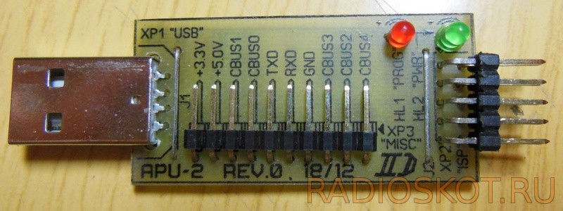
Schematic diagram of the USB programmer

This circuit simply directs the MOSI, MISO, SCK and RESET signals, which are generated at the DCD, DTR, RTS and DSR pins of the DD1 (FT232RL) chip, respectively, to the desired pins of the microcontroller being flashed (i.e., in fact, it is an analogue of the "ancient" programmers) . Moreover, it does this only at the moment of programming the stone, at other times the programmer is disconnected from the board being flashed due to 4 buffer elements of the DD2 chip (74HC125D). The state of the MOSI, MISO, SCK and RESET lines is set / read by the firmware on the computer. Data transfer between the PC and the FT232RL chip is via the USB bus (from which the programmer also receives power).

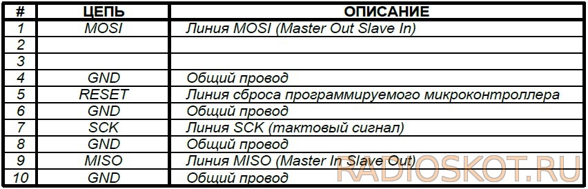
The HL2 LED (“PWR”) indicates that the programmer has been supplied with power from the USB bus. LED HL1 ("PROG") indicates the process of flashing the microcontroller (lights only during flashing). Here, in principle, is the entire description of the actual electrical circuit diagram. The only thing I would like to note: firstly, to connect the programmer to the board being flashed, an IDC-10MR connector (XP2 "ISP") is used, the pinout of which coincides with the widespread pinout of the programmer connector
STK200/STK300:
XP2 "ISP" connector for connecting the device to a programmable microcontroller
XP3 "MISC" connector for using additional programmer functions
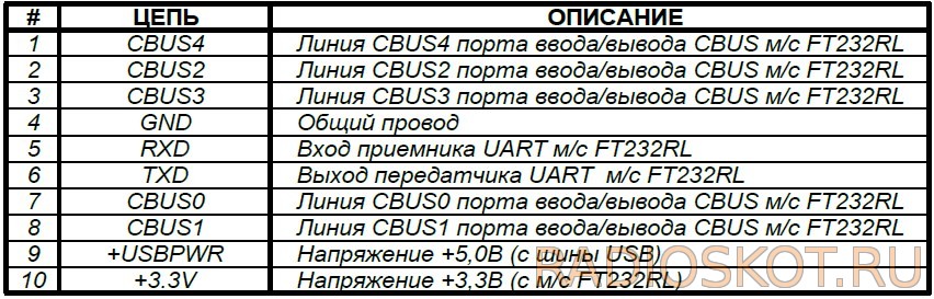
In general, the FT232RL chip has quite a lot of potential for the developer (for example, the CBUS bus lines can be used as ordinary microcontroller I / O lines), so it's nice to have access to all its pins. Well, access to voltages of +5.0 V and +3.3 V will never be superfluous either. In riveted circuit board and complete detailed description. Development and manual - [email protected] , trial - SssaHeKkk.
Discuss the article USB PROGRAMMER
Beginner Radio Amateur Competition
“My amateur radio design”
USB AVR programmer
Scheme and software simple high speed USB AVR programmer, which can be assembled with your own hands and a novice radio amateur
Competitive design of a novice radio amateur -
“USB AVR programmer”
Hello dear friends and visitors of the site!
I present to your court the second competitive work.
The author of the design Grigoriev Ilya Sergeevich.
Now on our site not only “The ice has broken”, but also “The meeting continues”.
USB AVR programmer
A little about this design.
At first glance, it seems that this scheme is complicated, not “too tough” for beginners, and the author is already a fairly experienced radio amateur.
I dare to assure everyone that Ilya Sergeevich is a novice radio amateur. And with his design, he proved that with desire, perseverance, determination, any novice radio amateur can assemble a design of such complexity.
Well, now, the word to the author.
Grigoriev Ilya Sergeevich, city of Khabarovsk
Hi all!
I present to your court my second completed work (the first is a simple flasher).
I decided that in the future I would assemble circuits based on any microcircuits that need to be programmed, which, in fact, requires a programmer!
There are a huge number of schemes on the Internet, for every taste, but the main problem and remark to the schemes is that I have neither LTP nor COM port, the USB programmer option remains. But even here there is a snag - for most programmers, to get started, their microcircuits need to be programmed to work, and for this you need ... - that's right, a programmer! It was possible, of course, to assemble the Gromov programmer, go through friends and find an LTP or COM port, but I didn’t want to. The last option remained - to use a programmer based on the FT232RL chip, the minus for this programmer and this chip is only the price of the latter - it costs around 230 rubles in Khabarovsk. I decided not to save on such money and take up the assembly of the programmer on the FT232RL.
So here's the parts list:
This is the heart of the programmer - FT232RL. Price - 230r
The second chip is 74HC244, it is needed, because this programmer has one more minus - it does not give the RESET line at the end of programming. Therefore, in order for the circuit to start, it is necessary to tear out the ISP connector from the board, which is very inconvenient. This can be solved by simply adding a 74HC244 buffer chip to this circuit. Price 20-30 r
And then a set of small things:
- 4 resistors of 47 ohms
- 4 resistors of 100 ohms
- 1 resistor at 4.7Kom
– 3 300 ohm resistors
– 3 conders at 0.1u
– 3 LEDs (s, h, g)
– 1 Schottky diode (for possible reverse current from the flashed device did not burn the programmer and PC)
– 1 USB type B, it is also called printer
That's all you need! Small things cost around 50 rubles
I took all the components in the usual version and smd, because. I didn’t fully know how my work with smd components would turn out, all of a sudden I would have to assemble a large version.
Here is the schema itself:
Principle of operation.
The programmer is powered by USB port a. The output levels of the programmer using the jumper JP1 can be set to either 5 volts or 3 volts.
The power supply voltage of the programmer can be applied through connector X2 to the board to be programmed, for which you need to close the jumper JP2.
It should be borne in mind that at 5 volt supply voltage is supplied from the USB port. And the maximum current that can be obtained from the programmer is limited to 500 mA. However, for this current, the FT232 chip must be configured using the FT Prog utility.
With a 3-volt supply, the voltage is taken from the output of the internal stabilizer of the FT232 microcircuit, the maximum current of which is about 50 mA.
To prevent power supply to the USB port from external device the programmer has a Schottky diode (they have a small voltage drop in the forward direction). If desired, the VD1 diode can be replaced with an ordinary diode or a jumper, but this one is at your own peril and risk.
Also, the programmer can be used as a USB-UART converter. To do this, the RXD, TXD signals are output to the X2 connector and the LED2, LED3 LEDs are connected. They flash when data is being transferred.
The programmer does not need to be disconnected from the board being programmed, because after programming, the DD1 chip switches the output buffers to the third state.
LED1 lights up when programming is in progress.
A clock signal can be output to pad JP. This requires the FT232 to be configured using the FT Prog utility.
The build process itself.
First, I printed the diagram on a glossy magazine sheet (I used both photo paper and adhesive paper for the printer, everything is not right ... the best effect is printing the diagram on a glossy magazine). Then, after connecting the glossy sheet with a piece of textolite, we begin to iron with an iron, setting the maximum temperature on it. First, I put the iron directly on the leaf so that it would stick to the textolite, held it for 10 seconds, then put a piece of paper on top and started ironing for 3-4 minutes, then removed the piece of paper and put the iron on for a few more seconds and with a sharp corner I moved the iron to the places where the future tracks for microcircuits will be.

After that, remove the iron, and let the board cool completely. Then we dip our textolite with a glossy paper in warm water for 5 minutes, so that the paper gets wet and it lags behind the textolite, then carefully roll up the paper. Here's what happens:

Then we poison. I poison with ferric chloride: I pour almost hot water, dissolve the powder in it, dip the textolite and then pour hot water into a basin and dip a bowl with ferric chloride there. The higher the concentration of the solution and the temperature, the faster the reaction will take place.
Here's what happened:

Then I took a cotton swab with acetone and removed the toner, then tinned it.
And began to solder:


I assembled the programmer, after which I MANDATORY checked everything for a short circuit. In general, since I worked with such a trifle for the first time, then after each resistor, after each conder, I checked the programmer for clearance (it is very clear whether the solder hit the adjacent tracks) and checked with a multimeter for a short circuit. The result is this - 2 times there were short circuits under the resistors ... I successfully fixed everything.
Also, after assembling the programmer, you should not immediately plug it into the USB port. Make sure that there are no short circuits between the ground and the power plus, set the jumpers to the required position and only then connect the programmer to the computer.
To be honest, I was worried, although I was sure that there was no short circuit.
After connecting, I felt the heating of the board, in the FT232RL area, and the PC issued a connection message unknown device with wrong work. I quickly turned off the programmer and again, carefully examined all the tracks for solder sticking to neighboring tracks and soldered all the microcircuit leads again. After that, I connected the programmer again and, lo and behold! , the programmer decided and asked to install firewood! I installed firewood and 2 new devices appeared in the application manager:

Hooray! Now you can seriously think about working with microcircuits!
Thank you for your attention!
(666.9 KiB, 2,785 hits)
Dear friends and guests of the site!
Do not forget to express your opinion on the competitive works and take part in discussions on the site's forum. Thank you.
In modern electronic circuits microcontrollers are being used more and more. But what is there to say, if today you can’t even find an ordinary Christmas garland without a microcontroller inside - it sets various illumination programs.
I first encountered microcontrollers when building my first . It was then that it turned out that the controller without firmware is just a piece of plastic with legs.
And in order to upload the necessary firmware to ATMEG, you can’t do without a programmer. Next, we will consider two of the simplest and most time-tested programmer circuits.
Scheme one
Using this programmer, you can flash almost any ATMEL AVR controller, you just need to check the pinout of the microcircuit.
The COM connector on the diagram is "mother".
Just in case, I bring the wiring printed circuit board for atmega8 (), although such a primitive circuit is easier to draw by hand. The board must be mirrored before printing. 
PCB file open with popular program Sprint Layout (if you haven't installed it yet, then it's better right away).
As is clear from the diagram, a negligible number of parts will be required to assemble the programmer: 
Instead of KT315, I stuck a BFR93A SMD transistor, which I had left after assembly.
Here is the complete programmer: 
I decided to take power (+ 5V) from the USB port.
If you have a new microcontroller (and no one has tried to flash it before), then quartz with accompanying capacitors can be omitted. Operation without a quartz resonator is possible due to the fact that the stone from the factory comes with a bit to the built-in generator and the circuit, accordingly, is clocked from it.
If your microcircuit is used, then without an external quartz it may not start. Then it is better to put quartz at 4 MHz, and capacitors are better at 33 pF.
As you can see, I did not install quartz with capacitors, but just in case, I provided places for them on the board.
It is best to upload the firmware using the PonyProg program (download).
Firmware with PonyProg
Go to the menu Setup -> Calibration -> Yes. The "Calibration OK" window should appear.
Now we plug the microcontroller into the programmer socket, and supply 5 volts of power (you can, for example, from a separate power source or USB port). Then click Command -> Read All.
After reading, the "Read successful" window appears. If everything is OK, then select the file with the required firmware for uploading: File -> Open Device File. Click "Open".
Now click Command -> Security and Configuration Bits and set the fuses you need.
That's all, MK is flashed and ready to use!
Keep in mind that when flashing with other programs (not PonyProg), the bits may be inverted! Then they should be set exactly the opposite. You can determine this by counting the fuses and looking at the "SPIEN" checkbox.
Scheme two
Another version of the programmer, with which you can upload the firmware to the ATMEG microcontroller (the so-called programmer of Gennady Gromov). The scheme consists of only 10 parts:  You can take any pulse diodes (for example, our KD510, KD522). Connector - "mother". Power supply to the MK (+5V) must be supplied separately, for example, from the same computer from the USB output.
All this can be assembled by surface mounting directly on the connector, but if you are a cool soldering iron and know what smd mounting is, you can do it beautifully: ___w1488.jpg)
Flashing algorithm using the Gromov programmer
We connect the programmer with the installed microcircuit to the COM port of the computer, then we start Uniprof, then we supply power to the microcontroller. And first of all, we check if the fuse bits are readable.
If everything is ok, select the file with the desired firmware and click record.
Be extremely careful and careful, because if it glitches when recording fuses, then the MK is either ejected or soldered to the doctor's circuit (and it is complicated). If you change the SPIEN bit to the opposite, the result will be the same (to the doctor).

Another simple, in terms of manufacturing, is a COM programmer. By using the Bitbang COM Port Alternate Mode, there is no need to convert the RS232 COM port interface to SPI required for programming. It remains only to bring the levels COM signals port (-12V, +12V) to the necessary (0, +5V). This is what makes
COM programmer diagram for AVR microcontrollers:
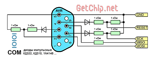
This programmer circuit is quite common and is known as the Gromov programmer. The name comes from the author of the program, Gennady Gromov, who proposed such a scheme.
To assemble the Gromov programmer, we need the following:
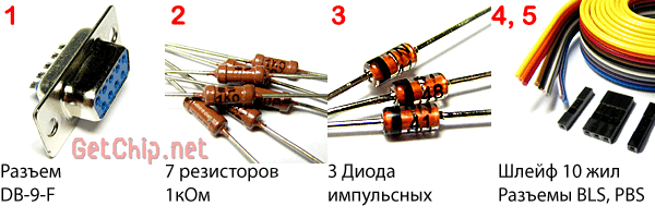
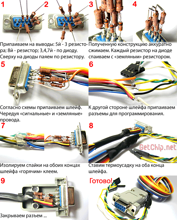
Diodes KD522, KD510, 1N4148 or the like. You can use any resistors you find. As a loop, you can use an IDE loop. When connecting a loop, for more stable operation of the programmer, each "signal" wire must alternate with a "ground" wire. This will reduce the level of noise induced in the lines and thereby increase the length of the programming wire. The length of the cable should be within 50 cm. You also need a connector for connecting to a programmable device.
For in-circuit programming, Atmel recommends standard connectors:

If you plan to get serious about microcontrollers, make the connectors standard. For one-time programming of the device, I recommend using it on the programmer (with such connectors to motherboard the buttons and LEDs of the computer case are connected - I took them) and the PLS “dad” pins on the board. This allows you to simplify the layout of the device board as much as possible, since the pins for the programmer are installed in close proximity near the legs of the microcontroller. The MOSI, MISO, SCK pins of AVR microcontrollers are always located together, so a built-in connector can be used for them. Separately, we make a connection for the "ground" -GND and "reset" -Reset.
Assembling a COM programmer is not difficult:
I deliberately do not give a printed circuit board for this programmer, since the circuit is simple and fiddling with the wiring and etching of the board simply does not justify itself.
In order for our COM programmer to work needed, to which we will connect the programmer and for the microcontroller.
- Since the Bitbang mode is non-standard for the computer's COM port, malfunctions are possible (although I did not have this). This is especially true for laptops. As a solution to this problem, we can recommend "playing around" with the COM port settings (speed, data bits, flow control options, buffer sizes ...).
- It is advisable to connect a separate "ground" connector first in order to equalize the potentials of the "ground" of the programmable device and the computer. For those who do not know, if your computer is plugged into a regular outlet, without a grounding contact, then due to the features of the filter of the computer's power supply, there is always a potential of 110V on the computer case.
Conclusion:
- Gromov's COM programmer is simple and reliable. I did not stop using it even after assembling a USB programmer (if any microcontroller stops being programmed by a USB programmer, I will definitely double-check it on the Gromov programmer).
- Since the Gromov programmer is assembled on passive elements, it does not require power for itself. Moreover, due to parasitic power, the microcontroller can be programmed without connecting a power source to it at all! Although I do not recommend programming like this, the fact itself is interesting.
— There is a nice bonus for Algorithm Builder users! This programmer can be used for in-circuit debugging of the crystal (JTAG software).


