A simple rhombic dmv antenna. Homemade antennas: outdoor, home
1. Do-it-yourself UHF television antenna
1.
Ring-coaxial cable PK75 530mm long.
2.
Loop-coaxial cable PK75 175mm long.
3.
To the antenna.
Assembly:
To assemble this antenna, you do not even have to run around the shops.
For this you need to take antenna cable PK75 530mm long (for the ring) and 175mm. (for loop).
Connect as shown in the figure.
Fasten to a sheet of plywood (plexiglass) using wire ties.
Direct to telecentre.
Here you have a UHF antenna that will work no worse than a purchased one.
2. Do-it-yourself television antenna DMV "Narodnaya"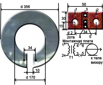
The antenna is an aluminum disk with an outer diameter of 356mm and an inner diameter of 170mm. and 1mm thick., in which a 10mm wide cut was made.
A printed circuit board made of fiberglass 1 mm thick is installed in place of the cut. This board has two holes for fixing with M3 screws.
TO printed circuit board attached to the antenna, solder the leads of the matching transformer T1.
For a transformer, it is best to use a ring core with an outer diameter of 6 ... 10 mm., Internal - 3 ... 7 mm. and 2…3 mm thick.
The transformer windings are superimposed with a single-layer insulated wire with a diameter of 0.2 ... 0.25 mm. and have the same number of turns, from 2 to 3 turns. The length of the turns of the turns is 20mm.
In the presence of such a transformer, reception is possible in the meter and decimeter range at a distance of 25 ... 30 km. At a distance of up to 50 km. the antenna works satisfactorily only on UHF channels.
Without a transformer, the reliable reception distance is halved.
However, there is a circuit that allows you to get similar results without a transformer, for this you need to assemble the following circuit: 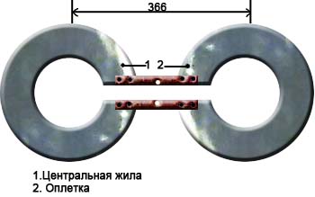
3. Do-it-yourself television log-periodic antenna (UHF).
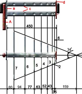

A. Mast
IN. Metal plate (dimensions 87x30x5)
WITH. metal tubes d 16…19mm
D. textolite plate (dimensions 87x30x5)
E. braid
F. coaxial cable
G. central vein
7,6,5,4,3,2,1. vibrators
Assembly
1. Take two metal tubes 450mm long and 16…19mm in diameter.
2. Make two plates with dimensions 87x30x5mm. (one of metal, the other of textolite), drill holes in them, as shown in the figures.
3. Fix the tubes in the plates (to the metal for soldering, and to the textolite with screws screwed from the ends of the plate with a diameter of 2.5 mm.
4. In metal tubes, along their length, at the distances indicated in the figure, drill holes with a diameter of 3.3 mm. and cut the M4 thread.
5. Screw into the holes 14 directors made of a bar with a diameter of 5 mm. At one end of each bar, cut an M4 thread, 10mm long.
The lengths of the directors, taking into account the part of the length of the threaded end, according to the number of the vibrator (see Fig.), are given in the table:
No. of vibrator…..length in mm…..number of pieces
1…………………………..107………………..2
2…………………………..129………………..2
3…………………………..155………………..2
4…………………………..186………………..2
5…………………………..225………………..2
6…………………………..272………………..2
7…………………………..330………………..2
6. Pass the coaxial cable in one of the tubes and unsolder it according to the figure. Paint the solder ends with paint.
7. Attach the antenna to the mast.
Antenna from user Evgen:
1. Take two EMPTY jars - for channels from 21 to 41 it is better than 0.5 l, for 42 - 69 - 0.33 l.
2. Fix them in any convenient way (duct tape, adhesive tape, rope, glue, etc.) on a solid piece of dielectric (rail, stick, piece of plywood - it is better to paint or varnish wood, textolite, getinax, etc.) on distance of 10 - 15 mm from each other.
3. We make holes of 2.5 - 4 mm along the edges of each jar (which screws-washers-gadgets are found) and with the help of these we attach the central core of the cable to one jar, and the braid to the other. You can attach any balancing device, but you can do without it.
The receiving distance depends on the installation location of this design (outside is better) and the power of the transmitter.
Holes are on those edges where the jars are closer to each other. And it’s more convenient to first fix the cable (and the balancing device - if you’re too lazy), and then the jars to the supporting structure.
Although cable and satellite television is developing at a rapid pace, the reception of on-air broadcasting is still relevant. For their operation, it is not at all necessary to buy a specialized product; you can assemble a high-quality log-periodic UHF antenna with your own hands. The manufacturing process itself must take place in accordance with elementary requirements and rules that are designed to protect the master from serious mistakes.
a brief description of
Every master knows that almost the entire volume of television broadcasting takes place in the UHF range. This trend is due to the economic side, since the antenna-feeder economy of broadcasting stations is greatly simplified, and the need for regular highly qualified service is also reduced. In addition, multifunctional TV transmitters cover almost all settlements with their powerful signal, and a well-developed network provides the program to the most remote corners of the country.

Innovative systems have influenced the fact that the method of broadcasting radio waves in large cities has changed significantly. Common interference affects a high-quality UHF antenna of the decimeter range quite weakly, but reinforced concrete high-rise buildings act as specific mirrors that transform the signal several times and even cause it to fade prematurely. Despite the possible difficulties, there are many different television programs on the air, which cannot but please the end user.
Separately, it is worth noting the fact that specialists have developed universal digital broadcasting. The DVB - T2 signal belongs to a special category. Digital TV broadcasting is practically insensitive to interference, but with phase distortion or mismatch with the cable, the final picture can crumble into small squares even with a clean signal.
Difficulties of choice
Many people think that choosing the right UHF antenna is quite simple, but in practice everything is different. The main difficulties are related to the fact that it is best to test such a product in the conditions in which it will be operated. This is due to the fact that each locality is characterized by an individual transmission of the radio signal.

Experts say that in laboratory conditions, TV antennas show some results, but in everyday life they are completely different. Among experienced craftsmen, there is a certain scheme, thanks to which it is possible to accurately determine the quality of work of both meter and decimeter products.
Of course, not a single seller will agree to give several models of antennas to test their performance at home. In this case, those characteristics that are indicated by the manufacturer in the accompanying documentation come to the rescue. As for the decimeter antenna, it is designed for beam pattern. The main parameters are the auxiliary (side) lobes, as well as their width. The chart parameters are determined both in the horizontal and vertical planes at the level of 0.7 from the maximum indicator.
The consumer can test various designs of receiving devices, but for this he need to create a level playing field:
- The cable that connects the TV and the antenna must have the same resistance level and length. It is advisable to use one wire, only receivers can be changed.
- The master must maintain the direction to the main source of the broadcast signal with high accuracy. To do this, you can put a mark on the mounting pipe.
- The location of the antenna plays an important role. For these purposes, a balcony, a roof or a roof can be used. The main thing is that the height and installation location are identical for all products.
- All measurements must be recorded under the same weather conditions.
Depending on the width of the main lobe, the DVM antenna can be directional or non-directional. This parameter is determined by the ratio of the allocated power, subject to the load matching at the time of signal reception from the main source. The shape of the diagram largely depends on the design of the antenna and the number of directors.
Main settings
Both outdoor and indoor UHF antenna must comply with a number of characteristics. Only a high-quality product can provide the end user with a clear TV signal.

Moreover, modern requirements for television antennas have changed significantly:

All these points are relevant for both analog and digital television.
Functionality
 A standard modern decimeter antenna is presented in the form of a specific set of high-quality elements: an active and passive installation, as well as several directors installed on one boom. The active element (vibrator) is always distinguished by its length, this part is located in the electromagnetic field of a certain radio signal, due to which it actively resonates at the frequency of the received signal. This device contains a specific electromotive force (EMF).
As for passive elements, they are affected by an electromagnetic field, which leads to the formation of (EMF). Due to this, they independently emit secondary electromagnetic fields. It is they who lead to active element additional electromotive force. All dimensions of passive parts and their distance to the vibrator must be selected in such a way that the EMF induced by them is in the same phase with the primary electromagnetic background.
In order for the reflector to function correctly, its length must be 15% longer than the vibrator. Such an antenna will have a one-way directional pattern in the horizontal and vertical planes. Thanks to this wizard, it will be possible to reduce the level of reception of reflected signals and fields that always pass from the thick side of the antenna. If the device is used for long distance operation or in difficult conditions, where there is a lot of specific interference, then you need to use a three-element antenna. Such a product should include a reflector, an active vibrator and at least two directors.
Homemade Antenna Options
 Despite the fact that the modern market offers all consumers a huge range of different products for receiving a TV signal, many craftsmen prefer to make them with their own hands. This trend arose against the background of the fact that ready-made home-made antennas have all the necessary operational and technical specifications. In addition, the master significantly saves his financial savings.
Original product from copper wire . In the arsenal of experienced craftsmen there is a high-quality and at the same time very simple version of a TV antenna, for the manufacture of which it is necessary to prepare only a piece of wire and a soldering iron. This is a frame loop product of a narrow range. Such an antenna has a significant advantage - it acts as a powerful selective filter that reduces interference. Thanks to this, the device can receive a high-quality signal.
To avoid common mistakes, you need to correctly determine the length of the loop. This can be done thanks to digital data, which are individual for each region. For example: in St. Petersburg, broadcasting takes place at a frequency of 666 and 586 MHz. But, regardless of the region of residence, the calculation formula is always the same: lr = 300/f. The length of the working loop in meters is denoted as lr, but the average frequency range is f. You can set the last value for St. Petersburg as follows (666+586)/2=626.
When all the data is available, you can safely determine the optimal length: lr 300/626 = 0.48, which means that the master will need 48 centimeters of wire. To make the finished product better and more durable for its manufacture, you can take a powerful RG-6 cable, where there is a special foil in the braid.
The manufacture of such an antenna must match the following diagram:
- Initially, the master must cut a piece of wire or cable RG -6, the length of which must fully correspond to the received lr data.
- A working loop of a suitable diameter is carefully folded, and after that a cable is soldered to it, which goes to the receiver. If the master decided to use a more durable RG -6, then before using it, insulation must be removed from both ends (about 2 centimeters). It is worth noting that the central core does not need to be cleaned, since it is not used in soldering.
- The finished receiver is installed on a special stand.
- A special plug (F-connector) is screwed onto the cable itself, which leads to the receiver.
An important fact is that, despite the simplicity of the design, this type of antenna is one of the most effective for receiving a digital signal. But, provided that all calculations were made as correctly as possible.
compact model
 Despite the unusual design of this antenna, it is quite functional, as it is presented in the form of the most common dipole. A huge advantage is that the dimensions of a standard beer can are ideally suited to the arms of an active UHF vibrator. When the finished product is installed indoors, the master does not need to coordinate the design with the cable at all (if its length does not exceed two meters).
Experienced craftsmen note that the arms of such an exotic dipole must always be fixed on a holder, which can be made of any insulating material. In this case, home craftsmen often use various improvised things (for example: a mop bar, a plastic clothes hanger, a wooden block). The distance between the shoulders should be from 1 to 9 cm (selected exclusively empirically). The main advantages of the design include the speed of its production - a maximum of 25 minutes, as well as the excellent quality of broadcasts.
Universal diamond-shaped signal receiver
This is one of the simplest, but at the same time durable and reliable antennas, which was in great demand in the era of on-air television. The device itself is presented as a simplified model of the classic zigzag.

Experts found that in order to increase the sensitivity, the unit must be equipped with capacitive inserts, as well as a powerful reflector. If the reception level is at high level, then it is not necessary to equip the product with additional elements at all.
As the main material, you can safely use brass, aluminum or copper tubes / strips with a width of 15 millimeters. If the master will install the finished structure on the street, then it is better to refuse aluminum products, since they are most susceptible to the negative effects of corrosion. Special capacitive inserts are made of strong tin, ordinary foil or metal mesh. After installation, they must be soldered along the entire contour. Professional cable laying also has its own nuances: the wire should not have any bends, and it should not leave the limits of the side insert.
It is not so difficult to make a high-quality log-periodic UHF antenna on your own, the main thing is adhere to the elementary recommendations of experts. Moreover, the installation of finished structures can take place both in the house and on the roof. But, it is important to remember that the higher the antenna is located, the better the quality of the received signal will be.
Good afternoon, V.Yu.
The visitor in the last posts with experience in FM radio antennas is me. The antenna turned out to be easy to manufacture and I decided to repeat it for FM reception and compare it with those previously made, by ear, according to instruments, ease of use. The goal was to obtain a signal with a minimum of interference for high-quality sound radio in stereo. Made two antennas. The first of the wire is 3 mm thick. The second is made of metal. From the metal-layer, it turned out to be slightly better in terms of the level of received signals. By ear - less low frequencies, more highs and the distinctness of each instrument in the orchestra.
Measurement method - there is a receiver with a signal level indicator in decibels. We number the stations of the FM band and look at the level of the received signal from the station in dB, then we summarize all the values. We get the numerical value of the antenna according to the received signal level parameter. All antennas were placed under the same conditions in direction. Wire on a window 303 cm long in the form of a rectangle with a gap along larger side in 2 cm (51 cm x 102 cm) - has a value of 491 dB, a directional loop phased loop antenna from a wire - 459 dB, the same from a metal-plastic - 485 dB. As can be seen from the presented values, the metal-plastic antenna is comparable to a full-size frame equal to the wavelength of the mid-FM band.
Now for the manufacturing technology. it is somewhat different from yours and is made without soldering. The base is a rail (30 x 6 x 3 cm). Remained from the repair (2 pcs). wire antenna- circumference 75 cm (quarter wave of the middle of the FM range). Two circles of the same length. We take a light self-tapping screw (not dark - it has a cone head) with a flat head for a Phillips screwdriver. We make a hole in the rail with a drill or in another way so that the wire enters the hole with little resistance. You can slightly bend the ends of the wire for this purpose. We put the two ends of the loop into the hole of the rail and do not connect them together (leave 5 mm between the ends of the loop). We do the same with the second loop at the other end of the rail. The distance from the end of the rail is 1 cm. We screw the screws on top of the rail so that the end of the screw enters the loop wire at the end. This ensures the contact of the coax with the frame. Under the screws, we wind the central core of the coax and the braid from different sides of the frame. For example, the central core is on the left, and the braid is on the right in the direction from the beginning of the rail to its end. Between the frames we lay the coaxial and fasten it to the screws (we wind it under the screw head). The second loop is also fastened and the ends of the coax are fastened under the screws for fastening the second loop. The descent in the form of a coaxial - I got a length of 7.5 meters, we fasten it under the screws of one of the frames (the central core is on the left, and the braid is on the right. self-tapping screws - 2 cm We connect the other end of the coax to the receiver through the connector you need.That's it - the antenna is ready.
Metal-plastic differs in manufacturability. Pipe 20 mm, also after repair. It bent into a ring without problems. The length of the loop is 75 - 1.5 cm (as recommended in the article) = 73.5 cm. Attaching the loop to the rail is also with a self-tapping screw, but larger so that it passes through the metal-layer and is well fixed to the tree, by 10-15 mm. There is a distance of 1 cm between the ends of one loop. The screws are still at a distance of 0.5 cm from the end of the loop. We get a distance of 2 cm between the screws of one loop. We lay a piece of metal-plastic between the loops and fasten it with screws to the rail, so that coax can be inserted inside. We connect the coaxial in the same way as in the first case to the ends of the loop, the central core and the braid. We ground the tube between the loops of the antenna (we connect it with a braid). We put a piece of coax into the pipe between the loops, connect the c.zh. and braid. We also connect the reduction coaxial with the screws of one of the loops (c.zh. and braid). We pre-clean the ends of the loops from vinyl to aluminum so that the screw head presses the wires to the aluminum and at the same time fastens the loop to the wooden rail.
With all respect, Andrew
1. Do-it-yourself UHF television antenna
1.
Ring-coaxial cable PK75 530mm long.
2.
Loop-coaxial cable PK75 175mm long.
3.
To the antenna.
Assembly:
To assemble this antenna, you do not even have to run around the shops.
To do this, you need to take the PK75 antenna cable 530mm long (for the ring) and 175mm. (for loop).
Connect as shown in the figure.
Fasten to a sheet of plywood (plexiglass) using wire ties.
Direct to telecentre.
Here you have a UHF antenna that will work no worse than a purchased one.
2. Do-it-yourself television antenna DMV "Narodnaya"
The antenna is an aluminum disk with an outer diameter of 356mm and an inner diameter of 170mm. and 1mm thick., in which a 10mm wide cut was made.
A printed circuit board made of fiberglass 1 mm thick is installed in place of the cut. This board has two holes for fixing with M3 screws.
The terminals of the matching transformer T1 are soldered to the printed circuit board attached to the antenna.
For a transformer, it is best to use a ring core with an outer diameter of 6 ... 10 mm., Internal - 3 ... 7 mm. and 2…3 mm thick.
The transformer windings are superimposed with a single-layer insulated wire with a diameter of 0.2 ... 0.25 mm. and have the same number of turns, from 2 to 3 turns. The length of the turns of the turns is 20mm.
In the presence of such a transformer, reception is possible in the meter and decimeter range at a distance of 25 ... 30 km. At a distance of up to 50 km. the antenna works satisfactorily only on UHF channels.
Without a transformer, the reliable reception distance is halved.
However, there is a circuit that allows you to get similar results without a transformer, for this you need to assemble the following circuit:
3. Do-it-yourself television log-periodic antenna (UHF).
A. Mast
IN. Metal plate (dimensions 87x30x5)
WITH. metal tubes d 16…19mm
D. textolite plate (dimensions 87x30x5)
E. braid
F. coaxial cable
G. central vein
7,6,5,4,3,2,1. vibrators
Assembly
1. Take two metal tubes 450mm long and 16…19mm in diameter.
2. Make two plates with dimensions 87x30x5mm. (one of metal, the other of textolite), drill holes in them, as shown in the figures.
3. Fix the tubes in the plates (to the metal for soldering, and to the textolite with screws screwed from the ends of the plate with a diameter of 2.5 mm.
4. In metal tubes, along their length, at the distances indicated in the figure, drill holes with a diameter of 3.3 mm. and cut the M4 thread.
5. Screw into the holes 14 directors made of a bar with a diameter of 5 mm. At one end of each bar, cut an M4 thread, 10mm long.
The lengths of the directors, taking into account the part of the length of the threaded end, according to the number of the vibrator (see Fig.), are given in the table:
No. of vibrator…..length in mm…..number of pieces
1…………………………..107………………..2
2…………………………..129………………..2
3…………………………..155………………..2
4…………………………..186………………..2
5…………………………..225………………..2
6…………………………..272………………..2
7…………………………..330………………..2
6. Pass the coaxial cable in one of the tubes and unsolder it according to the figure. Paint the solder ends with paint.
7. Attach the antenna to the mast.
Antenna from user Evgen:
1. Take two EMPTY jars - for channels from 21 to 41 it is better than 0.5 l, for 42 - 69 - 0.33 l.
2. Fix them in any convenient way (duct tape, adhesive tape, rope, glue, etc.) on a solid piece of dielectric (rail, stick, piece of plywood - it is better to paint or varnish wood, textolite, getinax, etc.) on distance of 10 - 15 mm from each other.
3. We make holes of 2.5 - 4 mm along the edges of each jar (which screws-washers-gadgets are found) and with the help of these we attach the central core of the cable to one jar, and the braid to the other. You can attach any balancing device, but you can do without it.
The receiving distance depends on the installation location of this design (outside is better) and the power of the transmitter.
Holes are on those edges where the jars are closer to each other. And it’s more convenient to first fix the cable (and the balancing device - if you’re too lazy), and then the jars to the supporting structure.
Once a good television antenna was in short supply, purchased quality and durability, to put it mildly, did not differ. Making an antenna for a “box” or “coffin” (an old tube TV) with your own hands was considered an indicator of skill. Interest in homemade antennas does not fade away even today. There is nothing strange here: TV reception conditions have changed dramatically, and manufacturers, believing that there is and will not be anything essentially new in the theory of antennas, most often adapt electronics to well-known designs, without thinking about the fact that The main thing for any antenna is its interaction with the signal on the air.
What has changed on the air?
Firstly, almost the entire volume of TV broadcasting is currently carried out in the UHF band. First of all, for economic reasons, it greatly simplifies and reduces the cost of the antenna-feeder economy of transmitting stations, and, more importantly, the need for its regular maintenance by highly qualified specialists engaged in hard, harmful and dangerous work.
Second - TV transmitters now cover almost all more or less populated places with their signal, and a developed communication network ensures the delivery of programs to the most remote corners. There, broadcasting in the habitable zone is provided by low-power, unattended transmitters.
Third, the conditions for the propagation of radio waves in cities have changed. On the UHF, industrial interference leaks weakly, but reinforced concrete high-rise buildings for them are good mirrors, repeatedly reflecting the signal until it is completely attenuated in the zone of seemingly confident reception.
Fourth - There are a lot of TV programs on the air now, dozens and hundreds. How diverse and meaningful this set is is another question, but it is now meaningless to count on receiving 1-2-3 channels.
Finally, development of digital broadcasting. The DVB T2 signal is something special. Where it still exceeds the noise even a little, by 1.5-2 dB, the reception is excellent, as if nothing had happened. And a little further or to the side - no, as cut off. The “digit” is almost insensitive to interference, but if there is a mismatch with the cable or phase distortions anywhere in the path, from the camera to the tuner, the picture can crumble into squares even with a strong clean signal.
Antenna Requirements
In accordance with the new reception conditions, the basic requirements for TV antennas have also changed:
- Its parameters such as directivity coefficient (CFA) and protective action coefficient (CPA) do not have a decisive value now: modern ether is very dirty, and for a tiny side lobe radiation patterns (DN), at least some kind of interference, let it crawl through, and you need to deal with it by means of electronics.
- Instead special meaning acquires its own antenna gain (KU). An antenna that “catches” the air well, and does not look at it through a small hole, will provide a power reserve for the received signal, allowing the electronics to clear it of noise and interference.
- A modern television antenna, with rare exceptions, must be a band antenna, i.e. its electrical parameters should be kept in a natural way, at the level of theory, and not squeezed into acceptable limits by engineering tricks.
- The TV antenna must be coordinated in the cable over its entire operating frequency range without additional matching and balancing devices (NCS).
- The frequency response of the antenna (AFC) should be as smooth as possible. Sharp surges and dips are inevitably accompanied by phase distortions.
The last 3 points are due to the requirements for receiving digital signals. Customized, i.e. operating theoretically at the same frequency, antennas can be "stretched" in frequency, for example. antennas of the "wave channel" type on the UHF with an acceptable signal-to-noise ratio capture channels 21-40. But their coordination with the feeder requires the use of OSS, which either strongly absorb the signal (ferrite), or spoil the phase response at the edges of the range (tuned). And such an antenna, which works perfectly on an “analog”, will receive a “digit” badly.
In this regard, from all the great antenna variety, this article will consider TV antennas available for self-manufacturing, of the following types:
- Frequency independent (all-wave)- is not different high parameters, but very simple and cheap, it can be done in just an hour. Outside the city, where the air is cleaner, it will be able to receive a digital or a fairly powerful analogue not a short distance from the television center.
- Range log-periodic. Figuratively speaking, it can be likened to a fishing trawl, which sorts prey when it is caught. It is also quite simple, perfectly consistent with the feeder in its entire range, absolutely does not change the parameters in it. The technical parameters are average, therefore it is more suitable for giving, and in the city as a room.
- Several modifications zigzag antenna , or Z-antennas. In the MV range, this is a very solid design that requires considerable skill and time. But on the UHF, due to the principle of geometric similarity (see below), it is so simplified and shrinks that it can be used as a highly efficient indoor antenna under almost any reception conditions.
Note: The Z-antenna, to use the previous analogy, is a frequent nonsense, raking up everything that is in the water. As the air became littered, it fell out of use, but with the development of digital TV, it again found itself on a horse - in its entire range it is just as perfectly coordinated and keeps the parameters as a “speech therapist”.
Precise matching and balancing of almost all the antennas described below is achieved by laying the cable through the so-called. point of zero potential. It has special requirements, which will be discussed in more detail below.
About vibrator antennas
Up to several tens of digital channels can be transmitted in the frequency band of one analog channel. And, as already mentioned, the figure works with an insignificant signal-to-noise ratio. Therefore, in places very remote from the television center, where the signal of one or two channels barely finishes, for receiving digital TV, the good old wave channel (AVK, wave channel antenna) from the class of vibrator antennas can also be used, so at the end we will devote a few lines and to her.
About satellite reception
do it yourself satellite dish there is no point. You still need to buy a head and a tuner, and behind the external simplicity of the mirror lies a parabolic oblique incidence surface, which not every industrial enterprise can perform with the required accuracy. The only thing that homemade people can do is set up a satellite dish, about that.
About antenna parameters
The exact determination of the antenna parameters mentioned above requires knowledge of higher mathematics and electrodynamics, but it is necessary to understand their meaning when starting to manufacture an antenna. Therefore, we give a somewhat rough, but still clarifying definition (see the figure on the right):

- KU - the ratio of the signal power received by the antenna to the main (main) lobe of its DN, to its same power, received in the same place and at the same frequency, omnidirectional, with a circular, DN, antenna.
- KND is the ratio of the solid angle of the entire sphere to the solid angle of the opening of the main lobe of the RP, assuming that its cross section is a circle. If the main lobe has different sizes in different planes, you need to compare the area of \u200b\u200bthe sphere and the cross-sectional area of \u200b\u200bit by its main lobe.
- CPD is the ratio of the signal power received to the main lobe to the sum of the interference powers at the same frequency received by all side (back and side) lobes.
Notes:
- If the antenna is a band antenna, the powers are considered at the frequency of the useful signal.
- Since there are no completely omnidirectional antennas, a half-wave linear dipole oriented in the direction of the electric field vector (along its polarization) is taken as such. Its KU is considered equal to 1. TV programs are transmitted with horizontal polarization.
It should be remembered that KU and KND are not necessarily interconnected. There are antennas (for example, "spy" - a single-wire traveling wave antenna, ABC) with high directivity, but unity or less gain. Such look into the distance as if through a diopter sight. On the other hand, there are antennas, eg. Z-antenna, in which low directivity is combined with significant gain.
About the intricacies of manufacturing
All elements of the antennas, through which the currents of the useful signal flow (specifically, in the descriptions of individual antennas), must be interconnected by soldering or welding. In any prefabricated assembly in the open air, electrical contact will soon be broken, and the parameters of the antenna will deteriorate sharply, up to its complete uselessness.
This is especially true for points of zero potential. In them, as experts say, there is a voltage node and current antinode, i.e. its greatest value. Current at zero voltage? Nothing surprising. Electrodynamics has gone from Ohm's law to DC as far as a T-50 from a kite.
Places with zero potential points for digital antennas are best made from bent solid metal. A small "creeping" current in welding when receiving an analogue in the picture, most likely, will not affect. But, if a figure is received at the noise boundary, then the tuner may not see the signal due to the “creep”. Which, with a pure current in the antinode, would give a stable reception.
About cable soldering
The braid (and often the central core) of modern coaxial cables are not made of copper, but of corrosion-resistant and inexpensive alloys. They solder poorly and if you heat for a long time, you can burn the cable. Therefore, you need to solder cables with a 40-watt soldering iron, low-melting solder and with flux paste instead of rosin or alcohol rosin. There is no need to spare the paste, the solder immediately spreads along the veins of the braid only under a layer of boiling flux.

Types of antennas
All-wave
An all-wave (more precisely, frequency-independent, CNA) antenna is shown in fig. She is two triangular metal plates, two wooden slats, and a lot of copper enameled wires. The diameter of the wire does not matter, and the distance between the ends of the wires on the rails is 20-30 mm. The gap between the plates to which the other ends of the wires are soldered is 10 mm.
Note: instead of two metal plates, it is better to take a square of one-sided foil fiberglass in triangles cut out on copper.
The width of the antenna is equal to its height, the opening angle of the canvases is 90 degrees. The cable laying diagram is shown in the same place in Fig. The point marked in yellow is the point of quasi-zero potential. It is not necessary to solder the cable sheath to the web in it, it is enough to tie it tightly, for coordination there will be enough capacity between the braid and the web.
CNA, stretched in a window 1.5 m wide, receives all meter and DCM channels from almost all directions, except for a dip of about 15 degrees in the canvas plane. This is its advantage in places where it is possible to receive signals from different television centers, it does not need to be rotated. Disadvantages - a single KU and zero KZD, therefore, in the zone of interference and outside the zone of reliable reception, the CHNA is not suitable.
Note : There are other types of NNA, for example. in the form of a two-turn logarithmic spiral. It is more compact than triangular canvases in the same frequency range, therefore it is sometimes used in technology. But in everyday life this does not give advantages, it is more difficult to make a spiral CNA, it is more difficult to coordinate with a coaxial cable, therefore we do not consider it.
Based on the CNA, a once very popular fan vibrator (horns, flyer, slingshot) was created, see fig. Its directivity and efficiency are something around 1.4 with a fairly smooth frequency response and linear phase response, so it would be suitable for digital even now. But - it works only on MV (channels 1-12), and digital broadcasting goes to UHF. However, in the countryside, when climbing 10-12 m, it can be suitable for receiving an analogue. The mast 2 can be made of any material, but the mounting straps 1 are made of a good non-wetting dielectric: fiberglass or fluoroplast with a thickness of at least 10 mm.

Beer all-wave

The all-wave antenna made of beer cans is clearly not the fruit of the hangover hallucinations of a drunken radio amateur. It's really very good antenna for all cases of reception, you just need to do it right. And extremely simple.
Its design is based on the following phenomenon: if you increase the diameter of the arms of a conventional linear vibrator, then its operating frequency band expands, while other parameters remain unchanged. Since the 1920s, long-distance radio communications have been using the so-called. Nadenenko dipole based on this principle. And beer cans are just right in size as the arms of a vibrator on the UHF. In essence, the PNA is a dipole, the arms of which expand indefinitely to infinity.
The simplest beer vibrator of two cans is suitable for indoor reception of an analogue in the city, even without coordination with the cable, if its length is not more than 2 m, on the left in fig. And if you assemble a vertical in-phase array from beer dipoles with a half-wave step (on the right in the figure), match it and balance it with the help of an amplifier from the Polish antenna (we will talk about it later), then due to the vertical compression of the main lobe of the DN, such an antenna will give and good ku.
The gain of the "pivnukha" can be further increased by adding at the same time a KZD, if a screen from the grid is placed behind it at a distance equal to half the lattice spacing. A beer grate is mounted on a dielectric mast; mechanical connections of the shield with the mast are also dielectric. The rest is clear from the next. rice.

Note: the optimal number of lattice floors is 3-4. With 2, the gain in gain will be small, and more difficult to match with the cable.
Video: manufacturing the simplest antenna from beer cans
"Speech therapist"
A log-periodic antenna (LPA) is a collecting line to which halves of linear dipoles (i.e., pieces of a conductor a quarter of the working wavelength) are alternately connected, the length and distance between which change exponentially with an exponent less than 1, in the center in Fig. The line can be either configured (with a short circuit at the end opposite the cable connection point) or free. An LPA on a free (unconfigured) line is preferable for receiving a digit: it comes out longer, but its frequency response and phase response are smooth, and matching with the cable does not depend on frequency, so we will stop at it.

LPA can be manufactured for any, up to 1-2 GHz, predetermined frequency range. When the operating frequency changes, its active region of 1-5 dipoles shifts back and forth along the canvas. Therefore, the closer the progression indicator is to 1, and, accordingly, the smaller the antenna opening angle, the greater the gain it will give, but at the same time its length increases. On the UHF, 26 dB can be achieved from an external LPA, and 12 dB from a room one.
LPA, we can say, in terms of the combination of qualities, an ideal digital antenna, so let's dwell on its calculation in more detail. The main thing to know is that an increase in the progression rate (tau in the figure) gives an increase in gain, and a decrease in the opening angle of the LPA (alpha) increases directivity. The screen for the LPA is not needed, it has almost no effect on its parameters.
The calculation of a digital LPA has the following features:
- They start it, for the sake of frequency margin, from the second longest vibrator.
- Then, taking the reciprocal of the progression rate, the longest dipole is calculated.
- After the shortest, based on the given frequency range, dipole, add one more.
Let's explain with an example. Let's say our digital programs lie in the range of 21-31 TVK, i.e. at 470-558 MHz in frequency; wavelengths, respectively - 638-537 mm. Let's also assume that we need to receive a weak noisy signal far from the station, so we take the maximum (0.9) progression indicator and the minimum (30 degrees) opening angle. For the calculation, you need half the opening angle, i.e. 15 degrees in our case. Opening can be further reduced, but the length of the antenna will increase exorbitantly, in terms of cotangent.
We consider B2 in Fig: 638/2 = 319 mm, and the dipole arms will be 160 mm each, you can round up to 1 mm. The calculation will need to be carried out until Bn = 537/2 = 269 mm is obtained, and then another dipole is calculated.
Now we consider A2 as B2 / tg15 \u003d 319 / 0.26795 \u003d 1190 mm. Then, through the progression indicator, A1 and B1: A1 = A2 / 0.9 = 1322 mm; B1 \u003d 319 / 0.9 \u003d 354.5 \u003d 355 mm. Then sequentially, starting with B2 and A2, we multiply by the indicator until we reach 269 mm:
- B3 \u003d B2 * 0.9 \u003d 287 mm; A3 \u003d A2 * 0.9 \u003d 1071 mm.
- H4 = 258 mm; A4 = 964 mm.
Stop, we already have less than 269 mm. We check whether we meet the gain, although it’s already clear that we don’t: in order to get 12 dB or more, the distances between the dipoles should not exceed 0.1-0.12 wavelengths. In this case, we have for B1 A1-A2 \u003d 1322 - 1190 \u003d 132 mm, and this is 132/638 \u003d 0.21 of the wavelength of B1. It is necessary to “pull up” the indicator to 1, to 0.93-0.97, so we try different ones until the first difference A1-A2 is halved or more. For a maximum of 26 dB, you need a distance between dipoles of 0.03-0.05 wavelengths, but not less than 2 dipole diameters, 3-10 mm on UHF.
Note: the rest of the line behind the shortest dipole, we cut it off, it is needed only for calculation. Therefore, the actual length of the finished antenna will be only about 400 mm. If our LPA is outdoor, this is very good: you can reduce the opening, getting more directivity and protection from interference.
Video: DVB T2 Digital TV Antenna
About line and mast
The diameter of the tubes of the LPA line on the DMV is 8-15 mm; the distance between their axes is 3-4 diameters. We also take into account that thin “lace-up” cables give such attenuation per meter to the UHF that all antenna-amplifying tricks will come to naught. The coaxial for the external antenna must be taken good, with a shell diameter of 6-8 mm. That is, the tubes for the line must be thin-walled seamless. It is impossible to tie the cable to the line from the outside, the quality of the LPA will drop sharply.
It is necessary, of course, to fasten the outer LPA to the mast by the center of gravity, otherwise the low windage of the LPA will turn into a huge and shaking one. But it is also impossible to connect a metal mast directly to the line: it is necessary to provide a dielectric insert at least 1.5 m long. The quality of the dielectric does not play a big role here, the oiled and painted wood will do.
About the Delta Antenna
If the UHF LPA is consistent with the amplifier cable (see below, about Polish antennas), then the shoulders of a meter dipole, linear or fan-shaped, can be attached to the line, like a "slingshot". Then we get a universal MV-UHF antenna of excellent quality. This solution is used in the popular Delta antenna, see fig.

Antenna "Delta"
Zigzag on air
The Z-antenna with a reflector gives the same gain and QPV as the LPA, but its main lobe is more than twice as wide horizontally. This may be important in the countryside, when there is TV reception from different directions. A decimeter Z-antenna has a small size in terms of size, which is essential for indoor reception. But its operating range is theoretically not unlimited, frequency overlap while maintaining parameters acceptable for digital - up to 2.7.

The design of the MV Z-antenna is shown in Figure; the cable path is highlighted in red. In the same place at the bottom left - a more compact ring version, colloquially - a "spider". It clearly shows that the Z-antenna was born as a combination of a CNA with a range vibrator; there is something in it from a rhombic antenna, which does not fit into the topic. Yes, the spider ring does not have to be wooden, it can be a metal hoop. "Spider" receives 1-12 MV channels; DN without a reflector is almost circular.
The classic zigzag works either on 1-5 or 6-12 channels, but for its manufacture you only need wooden slats, copper enameled wire c d = 0.6-1.2 mm and a few scraps of foil fiberglass, so we give dimensions, through shot for 1-5/6-12 channels: A = 3400/950 mm, B, C = 1700/450 mm, b = 100/28 mm, B = 300/100 mm. At point E - zero potential, here you need to solder the braid with a metallized base plate. The reflector dimensions are also 1-5/6-12: A = 620/175 mm, B = 300/130 mm, D = 3200/900 mm.
A range Z-antenna with a reflector gives a gain of 12 dB, tuned to one channel - 26 dB. In order to build a single-channel zigzag based on a range zigzag, you need to take the side of the square of the canvas in the middle of its width to a quarter of the wavelength and recalculate all other dimensions proportionally.
folk zigzag
As you can see, the MV Z-antenna is a rather complex structure. But its principle shows itself in all its splendor in the DMV. The UHF Z-antenna with capacitive inserts, which combines the advantages of "classics" and "spider", is so easy to make that it earned the title of people's in the USSR, see fig.

Material - copper tube or aluminum sheet with a thickness of 6 mm. The side squares are solid metal or covered with a mesh, or closed with a tin. In the last two cases, they need to be soldered along the contour. The coax cannot be bent sharply, so we guide it so that it reaches the side corner, and then does not go beyond the capacitive insert (side square). At point A (zero potential point), we electrically connect the cable sheath to the web.
Note: aluminum is not soldered with conventional solders and fluxes, therefore aluminum "folk" is suitable for outdoor installation only after sealing the electrical connections with silicone, because everything is screwed in it.
Video: Dual Delta Antenna Example
wave channel

The wave channel antenna (AVK), or the Udo-Yagi antenna available for self-production, is capable of giving the highest KU, KND and KZD. But it can receive a figure on the UHF only on 1 or 2-3 adjacent channels, tk. belongs to the class of sharply tuned antennas. Its parameters outside the tuning frequency deteriorate sharply. VKA is recommended to be used with very poor reception conditions, and for each TVK, make a separate one. Luckily, it's not very difficult - AVK is simple and cheap.
At the heart of the work of the AVC is the "raking" of the electromagnetic field (EMF) of the signal to the active vibrator. Outwardly small, light, with minimal windage, AVK can have an effective aperture of tens of wavelengths of operating frequency. Shortened and therefore having a capacitive impedance (impedance) directors (directors) direct the EMF to the active vibrator, and the reflector (reflector), elongated, with an inductive impedance, throws back to it what slipped by. Only 1 reflector is needed in AVK, but there can be from 1 to 20 or more directors. The more of them, the higher the amplification of the AVC, but the narrower its frequency band.
From the interaction with the reflector and directors, the wave impedance of the active (from which the signal is taken) of the vibrator drops the more, the closer the antenna is tuned to the gain maximum, and coordination with the cable is lost. Therefore, the active dipole AVK is made loop, its initial impedance is not 73 ohms, as in a linear one, but 300 ohms. At the cost of reducing it to 75 ohms, an AVC with three directors (five-element, see the figure on the right) can be tuned to almost a maximum gain of 26 dB. Characteristic for AVC RP in the horizontal plane is shown in fig. at the beginning of the article.
AVK elements are connected to the boom at zero potential points, so the mast and boom can be anything. Polypropylene pipes work very well.
The calculation and setting of AVK for analog and digital are somewhat different. For an analogue, the wave channel must be calculated for the carrier frequency of the image F and for a digital one, for the middle of the TVK spectrum Fc. Why so - here to explain, unfortunately, there is no place. For the 21st TVK Fi = 471.25 MHz; Fc = 474 MHz. UHF TVK are located close to each other through 8 MHz, so their tuning frequencies for AVC are calculated simply: Fn = Fi / Fc (21 TVK) + 8 (N - 21), where N is the number of the desired channel. Eg. for 39 TVK Fi = 615.25 MHz, and Fc = 610 MHz.
In order not to write down a lot of numbers, it is convenient to express the dimensions of the AVC in fractions of the operating wavelength (it is considered as L \u003d 300 / F, MHz). The wavelength is usually denoted by the small Greek letter lambda, but since there is no Greek alphabet by default on the Internet, we will conditionally denote it with a large Russian letter L.
The dimensions of the AVK optimized for the figure, according to Fig., are as follows:

- P = 0.52L.
- B \u003d 0.49L.
- D1 = 0.46L.
- D2 = 0.44L.
- D3 \u003d 0.43 l.
- a = 0.18L.
- b = 0.12L.
- c \u003d d \u003d 0.1L.
If you do not need a lot of gain, but it is more important to reduce the dimensions of the AVK, then D2 and D3 can be removed. All vibrators are made of a tube or rod with a diameter of 30-40 mm for 1-5 TVK, 16-20 mm for 6-12 TVK and 10-12 mm for UHF.
AVK requires precise matching with the cable. It is the careless implementation of the matching and balancing device (USS) that explains most of the failures of amateurs. The simplest CSS for AVK is a U-loop from the same coaxial cable. Its design is clear from Fig. on right. The distance between the signal terminals 1-1 is 140 mm for 1-5 TVK, 90 mm for 6-12 TVK and 60 mm for UHF.
Theoretically, the length of the knee l should be half the length of the working wave, as it appears in most publications on the Internet. But the EMF in the U-loop is concentrated inside the cable filled with insulation, so it is necessary (for a figure, it is especially necessary) to take into account its shortening factor. For 75-ohm coaxes, it ranges from 1.41-1.51, i.e. l you need to take from 0.355 to 0.330 wavelengths, and take it exactly so that the AVC is an AVC, and not a set of pieces of iron. The exact value of the velocity factor is always on the cable certificate.
Recently, the domestic industry has begun to produce reconfigurable AVK for digital, see fig. The idea, I must say, is excellent: by moving the elements along the boom, you can fine-tune the antenna to local reception conditions. It is better, of course, for a specialist to do this - the element-by-element setting of the AVK is interdependent, and the amateur will certainly get confused.

About "Poles" and amplifiers
Many users have polish antennas, who previously decently accepted an analogue, refuse to take a figure - it breaks, or even disappears altogether. The reason, I beg your pardon, is a bawdy-commercial approach to electrodynamics. It is sometimes a shame for colleagues who have made such a “miracle”: the frequency response and phase response look like either a psoriasis hedgehog, or a horse comb with broken teeth.
The only thing that is good about the "Polish women" is their amplifiers for the antenna. Actually, they do not allow these products to die ingloriously. First of all, the "bud" amplifiers are low-noise broadband. And, more importantly, with a high-impedance input. This allows, with the same strength of the EMF signal on the air, to apply several times more power to the tuner input, which makes it possible for the electronics to “tear out” the figure from the very ugly noises. In addition, due to the large input impedance, the Polish amplifier is an ideal CSS for any antenna: no matter what you connect to the input, the output is exactly 75 ohms without reflection and creep.
However, at very bad signal, outside the zone of reliable reception, the Polish amplifier no longer pulls. Power is supplied to it via cable, and power decoupling takes away 2-3 dB of the signal-to-noise ratio, which may just not be enough for the figure to go into the very outback. Needed here good amplifier TV signal with separate power supply. It will most likely be located near the tuner, and the OSS for the antenna, if required, will have to be done separately.

The scheme of such an amplifier, which showed almost 100% repeatability even when performed by novice radio amateurs, is shown in Fig. Gain adjustment - potentiometer P1. Decoupling chokes L3 and L4 are standard purchased. Coils L1 and L2 are made according to the dimensions in the wiring diagram on the right. They are part of the bandpass signal filters, so small deviations in their inductance are not critical.
However, the topology (configuration) of the installation must be observed exactly! And in the same way, a metal shield is also required, separating the output circuits from the other circuit.
Where to begin?
We hope that even experienced craftsmen will find some useful information in this article. And for beginners who do not yet feel the ether, it is best to start with a beer antenna. The author of the article, by no means and by no means an amateur in this field, at one time was quite surprised: the simplest "beer" with ferrite matching, as it turned out, and the MV takes no worse than the tested "slingshot". And what is worth doing one and the other - see the text.
(2
ratings, average: 4,00
out of 5)
And on the roof there was a satisfactory reception for the Pole. I have 70-80 kilometers to the TV center. These are my problems. From the balcony it is possible to catch 3-4 pieces from 30 channels, and then with “cubes”. I sometimes watch TV channels from the Internet on the computer in my room, and my wife in her TV cannot watch her favorite channels normally. Neighbors advise to install cable, but you have to pay for it every month, and I already pay for the Internet, and the pension is not rubber. We pull it all, we pull it, and it’s not enough for everything.
Peter Kopitonenko said:
It is impossible to put an antenna on the roof of the house, the neighbors swear that I go and break the roofing material of the roof and then their ceiling leaks. Actually, I am very “thankful” to that economist who received a bonus for saving himself. I came up with the idea of \u200b\u200bremoving an expensive gable roof from houses and replacing it with a flat roof covered with bad roofing material. The economist received money for saving, and people on the upper floors now suffer all their lives. Water flows on their heads and on the bed. They change the roofing material every year, and it becomes unusable during the season. In frosty weather, it cracks and rainwater and snow flows into the apartment, even if no one walks on the roof!!!
Sergei said:
Greetings!
Thanks for the article, but who is the author (I don’t see the signature)?
LPA according to the above method works fine, UHF 30 and 58 channels. Tested in the city (reflected signal) and outside the city, distances to the transmitter (1 kW) respectively: 2 and 12 km approximately. Practice has shown that there is no urgent need for the “B1” dipole, but another dipole in front of the shortest has a significant effect, judging by the signal intensity in%. Especially in the conditions of the city, where it is necessary to catch (in my case) the reflected signal. only I made an antenna with a “short circuit”, it happened, it just didn’t turn out to be a suitable insulator.
In general, I recommend.
Vasily said:
IMHO: people looking for an antenna for receiving ETsTV, forget about LPA. These wide-range antennas were created in the second half of the 50s (!!) of the last century in order to catch foreign television centers while being on the shores of the Soviet Baltic. In the magazines of the time, this was bashfully called "ultra-long reception." Well, they loved to watch Swedish porn on the Riga seashore at night ...
In terms of destination, I can say the same about “double, triple, etc. squares", as well as any "zigzags".
Compared to a “wave channel” similar in range and gain, LPA is more bulky and material-intensive. The calculation of the LPA is complex, intricate and looks more like guessing and adjusting the results.
If ETsTV is broadcasting in your region on neighboring UHF channels (I have 37-38), then The best decision search online for a book: Kapchinsky L.M. TV antennas(2nd edition, 1979) and make a “wave channel” for a group of UHF channels (if you broadcast above 21-41 channels, you will have to recalculate) described on page 67 and further (Fig. 39, table 11).
If the antenna can be simplified 15 - 30 km to the transmitter by making it four - five element, simply without installing the directors D, E and G.
For very close transmitters I recommend indoor antennas, by the way, in the same book on pages 106 - 109, drawings of wide-range room "wave channel" and LPA are given. The "wave channel" is visually smaller, simpler and more elegant with more gain!
By clicking the "Add comment" button, I agree to the site.