Do-it-yourself powerful UHF antenna. A simple homemade antenna for receiving terrestrial digital television
Good afternoon, dear readers. I haven’t written on the blog for a long time, due to the May holidays and a lot of work. But I managed to make one craft, very simple and useful - an antenna for digital TV with my own hands. At the same time, I’ll tell you, everything is quite simple.
Of course, cases are different, but before making this antenna, think: do you need it or not. This is what I'm getting at: nowadays it's easier to buy a digital antenna than to make it. If you just want to watch digital TV at home, constantly and preferably without interruptions, or the tower is far from your home, then it is better to seek advice and buy a good antenna in a store.
You need to understand that if you are making an antenna for the first time, you have little experience in electronics, or maybe none at all, then no one will be responsible for the fact that the antenna either will not work at all, or will stop working, and so on.
Personally, I don’t understand much about electronics, but I test what I do in practice and try to understand it as much as possible. The antenna samples presented below are quite simple and easy to manufacture.
Of course, if you need an antenna for a dacha where you rarely go, then a homemade antenna for digital TV with your own hands is perfect. I won’t bore you with calculations and various terms, I’ll just show and tell you, and you choose and try.
Write comments after the article, leave your opinion and, if there are errors, tell everyone about them.
I'll start with this antenna, since I made it myself for the first time. It seemed to me not difficult and at the same time quite powerful. Other sites said it was homemade. But I made it for my mother-in-law, in the village, where it was about 80 km from the broadcast tower to the antenna.
Butterfly antenna
My mother-in-law has been using it for more than two years now and there are practically no problems. Such an antenna is no different from a regular decimeter antenna. It is easier to remake a simple array-type antenna, which can be purchased at a low price in trading network, for digital, which will receive satellite (T2) channels.
But you can also make such an antenna for digital TV with your own hands, if you have everything you need, quickly and easily.
We will need:
- board or plywood measuring at least 550x70x5 mm;
- copper wire with a central core Ø 4 mm (6 mm is possible) - 4 m;
- self-tapping screws with caps (or buy washers separately);
- coaxial television cable;
- antenna F-plug;
- screwdriver or screwdriver;
- knife or scalpel; soldering iron;
- solder;
- flux paste;
- ruler or tape measure;
- wire cutters;
- pencil.
We find a board according to size, approximately and mark it as in the picture.
board markingEverything here is indicated in inches, let's translate. 1 inch equals 2.5 cm, it's simple.
We cut 8 wires 37.5 cm long. We strip the middle of each wire by 2 cm.

We bend each wire with the letter V so that the distance between the wires (its ends) is 7.5 cm.
We cut off 2 wires 42 cm long. We strip these 2 wires at the points of attachment to the board or plywood.
Step 5.
Then I cut two more pieces from the same wire to bring the wires from the center to the back wall of the board. Here you can see the dimensions for yourself, or you can avoid making them at all and attach the wire to the front wall.
We assemble all the wires using self-tapping screws, as shown in the figure at the beginning of the article.
Now let's work with a soldering iron. We only need this plug for the correct resistance so that it is 75 ohms at the output.
To do this, open the lid and do as in the picture below. I screwed the cap itself to the antenna.

Then we attach everything in a convenient place and then the antenna itself. Let's try and use it.
 This is how I did it
 I have had this antenna for over 2 years now. The only thing is that sometimes the antennae themselves bend, as if a strong wind bends or heavy birds perch. But everything can be fixed, I removed it, corrected it and continue to use it.
By the way, I tried without this plug, so as not to suffer, everything works, only a little worse.
Wire antenna with amplifier.
Here is another antenna for digital TV with your own hands, perfect for a country house or village. We make everything out of copper wire, and the amplifier can be taken from an old antenna or bought in a store.
What we need:
- Two pieces of wire 180 cm each;
- Amplifier (old one will do);
- A piece of metal or wood plate 15 cm * 15 cm;
- A drill or screwdriver, or a welding machine;
- Small bolts with nuts;
- Hammer;
- TV cable of suitable length.
First, we bend the pieces of wire into a diamond shape with sides of 45 cm. This is the optimal length. But if you make calculations for specific frequencies, then the length will be different, but this is for advanced people.
Now we immediately drill holes on the plate in the places where the diamonds are attached, flatten the ends, which we immediately attach to the amplifier. If the plate is metal, then use a welder to attach the catchers to it and that’s it.
We twist everything together and screw the TV cable wires to the amplifier.
Now we attach the antenna to the mast and point it towards the tower. We use it.
Please note that the entire antenna is painted. This will avoid corrosion and the DIY digital TV antenna will last longer.
Beer cans will help you.
This antenna picks up many different channels well. It is better, of course, to use it indoors and where the repeater tower is not far away.

We will need:
- 2 tin cans of 750 or 1000 ml;
- Coaxial television cable (RK75);
- Antenna plug;
- Electrical tape or tape;
- Self-tapping screws for metal;
- A polypropylene pipe or wooden stick for attaching cans to it;
- Screwdriver;
- Wire cutters;
- Needle file;
- Ruler.
Using a screwdriver, make 1 hole in the neck of each can, making sure that it does not become deformed.
Screw the screws into these holes using a screwdriver.
Step 2.
Clean the ends of the cable with a knife, not forgetting to remove the varnish from the copper wire with a file; screw the wire and cable braid twisted into a ring to the self-tapping screws (it will be more reliable if it is welded or soldered, but this is only if you have the appropriate tool).
Securely secure the cans to a pipe or stick using electrical tape or tape for this purpose, maintaining the distance between the cans (it has long been established experimentally, and this size is 7.5 cm).
Attach a plug to the other end of the cable, which will connect the cable to the receiving device.
Place the antenna in the required location, i.e. where signal reception will be ideal. The most painstaking work is preparing the RK75 cable. One end must be cleaned from the top shell at a distance of 10-12 cm with a knife without damaging the copper braid. Next, you need to twist this braid into a pigtail and remove the aluminum screen. After this, cut off the polyethylene sheath by 6-7 cm and expose the central core. The resulting copper strand and bare core are then attached to the cans. The second end of the cable must also be cleaned and a plug consisting of 2 halves must be connected to it.
The central core of the cable passes through the hole in one half of the plug, and the braid is connected to the plug body. Both halves are screwed on one another, and you get a reliable device for connecting to the antenna socket of the TV.
If you plan to place an antenna made from tin cans outdoors, then it must be reliably protected from external weather influences. Plastic bottles are suitable; you need to cut off the neck and bottom and place the antenna elements in them. In such conditions, it will reliably carry out the functions assigned to it.
This is the simplest broadband antenna, made from scrap materials without the use of special tools, and it is made quickly. You can make it yourself and install it in 20-30 minutes. You can make sure that your homemade antenna receives most channels satellite television, including TVB-T2. At a minimum, it receives up to 15 channels.
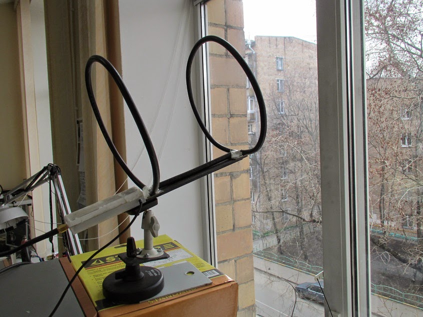
Antenna figure eight.
Once upon a time, when there was no digital TV yet, we made such an antenna at school. It is quite simple to manufacture and picks up the signal very well.
It’s a lot to write, and I haven’t made it myself for a long time, here you can watch the video:
Of course, such an antenna is not prohibited, this video just describes the process well.
Buy or find copper wire with a cross-section of 2 - 3 mm. in isolation. Bend the antenna to the dimensions indicated by the author of the video, minimally strip the soldering areas of insulation, solder the cable and seal it from moisture.
Yes, if not copper wire use aluminum, not much will be lost. The grille can be made from wire, not critical, even from an old refrigerator. If you are in an area of good reception, then it is not necessary to install a grille at all; this is digital and not analogue TV where repetitions on the screen can be observed due to the reflected signal.
What I like about this type of antenna is that it is easy to manufacture, does not require a filter for matching, and has good characteristics. You can increase the power of the antenna if you make it from four squares; you also make a cable tap from the middle, the closest distance between the conductors is 10 mm.
Well, here we have an antenna for digital TV with our own hands and different ways. That's all for me, leave your comments below, also join us in Odnoklassniki. Bye everyone and see you later.
Once upon a time, a good television antenna was in short supply; purchased ones did not differ in quality and durability, to put it mildly. Making an antenna for a “box” or “coffin” (an old tube TV) with your own hands was considered a sign of skill. Interest in homemade antennas continues to this day. There is nothing strange here: the conditions for TV reception have changed dramatically, and manufacturers, believing that there is and will not be anything significantly new in the theory of antennas, most often adapt electronics to long-known designs, without thinking about the fact that The main thing for any antenna is its interaction with the signal on the air.
What has changed on air?
Firstly, almost the entire volume of TV broadcasting is currently carried out in the UHF range. First of all, for economic reasons, it greatly simplifies and reduces the cost of the antenna-feeder system of transmitting stations, and, more importantly, the need for its regular maintenance by highly qualified specialists engaged in hard, harmful and dangerous work.
Second - TV transmitters now cover almost all more or less populated areas with their signal, and a developed communication network ensures the delivery of programs to the most remote corners. There, broadcasting in the habitable zone is provided by low-power, unattended transmitters.
Third, the conditions for the propagation of radio waves in cities have changed. On the UHF, industrial interference leaks in weakly, but reinforced concrete high-rise buildings are good mirrors for them, repeatedly reflecting the signal until it is completely attenuated in an area of seemingly reliable reception.
Fourth - There are a lot of TV programs on air now, dozens and hundreds. How diverse and meaningful this set is is another question, but counting on receiving 1-2-3 channels is now pointless.
Finally, digital broadcasting has developed. The DVB T2 signal is a special thing. Where it still exceeds the noise even just a little, by 1.5-2 dB, the reception is excellent, as if nothing had happened. But a little further or to the side - no, it’s cut off. Digital is almost insensitive to interference, but if there is a mismatch with the cable or phase distortion anywhere in the path, from the camera to the tuner, the picture can crumble into squares even with a strong clean signal.
Antenna requirements
In accordance with the new reception conditions, the basic requirements for TV antennas have also changed:
- Its parameters such as the directivity coefficient (DAC) and the protective action coefficient (PCA) are now of no decisive importance: modern ether is very dirty, and side lobe directional pattern (DP), at least some kind of interference will get through, and you need to fight it using electronic means.
- In return, the antenna's own gain (GA) becomes especially important. An antenna that catches the air well, rather than looking at it through a small hole, will provide a reserve of power for the received signal, allowing the electronics to clear it of noise and interference.
- A modern television antenna, with rare exceptions, must be a range antenna, i.e. its electrical parameters must be preserved naturally, at the level of theory, and not squeezed into acceptable limits through engineering tricks.
- The TV antenna must be coordinated with the cable over its entire operating frequency range without additional devices coordination and balancing (USS).
- The amplitude-frequency response of the antenna (AFC) should be as smooth as possible. Sharp surges and dips are certainly accompanied by phase distortions.
The last 3 points are determined by the requirements for receiving digital signals. Customized, i.e. Working theoretically at the same frequency, antennas can be “stretched” in frequency, for example. antennas of the “wave channel” type on the UHF with an acceptable signal-to-noise ratio capture channels 21-40. But their coordination with the feeder requires the use of USSs, which either strongly absorb the signal (ferrite) or spoil the phase response at the edges of the range (tuned). And such an antenna, which works perfectly on analogue, will receive “digital” poorly.
In this regard, from all the great variety of antennas, this article will consider TV antennas available for self-made, the following types:
- Frequency independent (all-wave)- is not different high parameters, but very simple and cheap, it can be done in literally an hour. Outside the city, where the airwaves are cleaner, it will be able to receive digital or a fairly powerful analogue not a short distance from the television center.
- Range log-periodic. Figuratively speaking, it can be likened to a fishing trawl, which sorts the prey during fishing. It is also quite simple, fits perfectly with the feeder throughout its entire range, and does not change its parameters at all. The technical parameters are average, so it is more suitable for a summer residence, and in the city as a room.
- Several modifications zigzag antenna , or Z-antennas. In the MV range, this is a very solid design that requires considerable skill and time. But on the UHF, due to the principle of geometric similarity (see below), it is so simplified and shrunk that it can well be used as a highly effective indoor antenna under almost any reception conditions.
Note: The Z-antenna, to use the previous analogy, is a frequent flyer that scoops up everything in the water. As the air became littered, it fell out of use, but with the development of digital TV, it was once again on the high horse - throughout its entire range, it is just as perfectly coordinated and keeps the parameters as a “speech therapist.”
Precise matching and balancing of almost all antennas described below is achieved by laying the cable through the so-called. zero potential point. It has special requirements, which will be discussed in more detail below.
About vibrator antennas
In the frequency band of one analog channel, up to several dozen digital ones can be transmitted. And, as already said, the digital works with an insignificant signal-to-noise ratio. Therefore, in places very remote from the television center, where the signal of one or two channels barely reaches, the good old wave channel (AVK, antenna wave channel), from the class, can be used for receiving digital TV vibrator antennas, so at the end we’ll devote a few lines to her.
About satellite reception
Do it yourself satellite dish there's no point. You still need to buy a head and a tuner, and behind the external simplicity of the mirror lies a parabolic surface of oblique incidence, which not every industrial enterprise can produce with the required accuracy. The only thing homemade people can do is set up a satellite dish, about that.
About antenna parameters
Accurate determination of the antenna parameters mentioned above requires knowledge of higher mathematics and electrodynamics, but it is necessary to understand their meaning when starting to manufacture an antenna. Therefore, we will give somewhat rough, but still clarifying definitions (see figure on the right):

- KU is the ratio of the signal power received by the antenna on the main (main) lobe of its DP to its same power received in the same place and at the same frequency by an omnidirectional, circular, DP antenna.
- KND is the ratio of the solid angle of the entire sphere to the solid angle of the opening of the main lobe of the DN, assuming that its cross section is a circle. If the main petal has different sizes in different planes, you need to compare the area of the sphere and the cross-sectional area of the main lobe.
- SCR is the ratio of the signal power received at the main lobe to the sum of the interference powers at the same frequency received by all secondary (back and side) lobes.
Notes:
- If the antenna is a band antenna, the powers are calculated at the frequency of the useful signal.
- Since there are no completely omnidirectional antennas, a half-wave linear dipole oriented in the direction of the electric field vector (according to its polarization) is taken as such. Its QU is considered equal to 1. TV programs are transmitted with horizontal polarization.
It should be remembered that CG and KNI are not necessarily interrelated. There are antennas (for example, “spy” - single-wire traveling wave antenna, ABC) with high directivity, but single or lower gain. These look into the distance as if through a diopter sight. On the other hand, there are antennas, e.g. Z-antenna, which combines low directivity with significant gain.
About the intricacies of manufacturing
All antenna elements through which useful signal currents flow (specifically, in the descriptions of individual antennas) must be connected to each other by soldering or welding. In any prefabricated unit in the open air, the electrical contact will soon be broken, and the parameters of the antenna will deteriorate sharply, up to its complete unusability.
This is especially true for points of zero potential. In them, as experts say, there is a voltage node and a current antinode, i.e. its greatest value. Current at zero voltage? Nothing surprising. Electrodynamics has moved away from Ohm's law by DC as far as a T-50 from a kite.
Places with zero potential points for digital antennas are best made bent from solid metal. A small “creeping” current in welding when receiving the analogue in the picture will most likely not affect it. But, if a digital signal is received at the noise level, then the tuner may not see the signal due to the “creep”. Which, with pure current at the antinode, would give stable reception.
About cable soldering
The braid (and often the central core) of modern coaxial cables is made not of copper, but of corrosion-resistant and inexpensive alloys. They solder poorly and if you heat them for a long time, you can burn out the cable. Therefore, you need to solder the cables with a 40-W soldering iron, low-melting solder and with flux paste instead of rosin or alcohol rosin. There is no need to spare the paste; the solder immediately spreads along the veins of the braid only under a layer of boiling flux.

Types of antennas
All-wave
An all-wave (more precisely, frequency-independent, FNA) antenna is shown in Fig. It consists of two triangular metal plates, two wooden slats, and a lot of enameled copper wires. The diameter of the wire does not matter, and the distance between the ends of the wires on the slats is 20-30 mm. The gap between the plates to which the other ends of the wires are soldered is 10 mm.
Note: Instead of two metal plates, it is better to take a square of one-sided foil fiberglass with triangles cut out of copper.
The width of the antenna is equal to its height, the opening angle of the blades is 90 degrees. The cable routing diagram is shown there in Fig. The point marked in yellow is the point of quasi-zero potential. There is no need to solder the cable braid to the fabric in it, just tie it tightly, and the capacity between the braid and the fabric will be enough for matching.
The CHNA, stretched in a window 1.5 m wide, receives all meter and DCM channels from almost all directions, except for a dip of about 15 degrees in the plane of the canvas. This is its advantage in places where it is possible to receive signals from different television centers; it does not need to be rotated. Disadvantages - single gain and zero gain, therefore, in the interference zone and outside the zone of reliable reception, the CNA is not suitable.
Note : There are other types of CNA, for example. in the form of a two-turn logarithmic spiral. It is more compact than the CNA made of triangular sheets in the same frequency range, therefore it is sometimes used in technology. But in everyday life this does not provide any advantages, it is more difficult to make a spiral CNA, and it is more difficult to coordinate with a coaxial cable, so we are not considering it.
Based on the CHNA, the once very popular fan vibrator (horns, flyer, slingshot) was created, see fig. Its directivity factor and coefficient of performance are something around 1.4 with a fairly smooth frequency response and linear phase response, so it would be suitable for digital use even now. But - it works only on HF (channels 1-12), and digital broadcasting is on UHF. However, in the countryside, with an elevation of 10-12 m, it may be suitable for receiving an analogue. Mast 2 can be made of any material, but fastening strips 1 are made of a good non-wetting dielectric: fiberglass or fluoroplastic with a thickness of at least 10 mm.

Beer all-wave

The all-wave antenna made from beer cans is clearly not the fruit of the hangover hallucinations of a drunken radio amateur. It's really very good antenna for all cases of reception, you just need to do it correctly. And it’s extremely simple.
Its design is based on the following phenomenon: if you increase the diameter of the arms of a conventional linear vibrator, then its operating frequency band expands, but other parameters remain unchanged. In long-distance radio communications, since the 20s, the so-called Nadenenko's dipole based on this principle. And beer cans are just the right size to serve as the arms of a vibrator on the UHF. In essence, the CHNA is a dipole, the arms of which expand indefinitely to infinity.
The simplest beer vibrator made of two cans is suitable for indoor analogue reception in the city, even without coordination with the cable, if its length is no more than 2 m, on the left in Fig. And if you assemble a vertical in-phase array from beer dipoles with a step of half a wave (on the right in the figure), match it and balance it using an amplifier from a Polish antenna (we will talk about it later), then thanks to the vertical compression of the main lobe of the pattern, such an antenna will give good CU.
The gain of the “tavern” can be further increased by adding a CPD at the same time, if a mesh screen is placed behind it at a distance equal to half the grid pitch. The beer grill is mounted on a dielectric mast; The mechanical connections between the screen and the mast are also dielectric. The rest is clear from the following. rice.

Note: the optimal number of lattice floors is 3-4. With 2, the gain in gain will be small, and more is difficult to coordinate with the cable.
Video: making a simple antenna from beer cans
"Speech therapist"
A log-periodic antenna (LPA) is a collecting line to which halves of linear dipoles (i.e., pieces of conductor a quarter of the operating wavelength) are alternately connected, the length and distance between which vary in geometric progression with an index less than 1, in the center in Fig. The line can be either configured (with a short circuit at the end opposite to the cable connection) or free. An LPA on a free (unconfigured) line is preferable for digital reception: it comes out longer, but its frequency response and phase response are smooth, and the matching with the cable does not depend on frequency, so we will focus on it.

The LPA can be manufactured for any predetermined frequency range, up to 1-2 GHz. When the operating frequency changes, its active region of 1-5 dipoles moves back and forth along the canvas. Therefore, the closer the progression indicator is to 1, and accordingly the smaller the antenna opening angle, the greater the gain it will give, but at the same time its length increases. At UHF, 26 dB can be achieved from an outdoor LPA, and 12 dB from a room LPA.
LPA can be said to be an ideal digital antenna based on its totality of qualities, so let’s look at its calculation in a little more detail. The main thing you need to know is that an increase in the progression indicator (tau in the figure) gives an increase in gain, and a decrease in the LPA opening angle (alpha) increases the directivity. A screen is not needed for the LPA; it has almost no effect on its parameters.
Calculation of digital LPA has the following features:
- They start it, for the sake of frequency reserve, with the second longest vibrator.
- Then, taking the reciprocal of the progression index, the longest dipole is calculated.
- After the shortest dipole based on the given frequency range, another one is added.
Let's explain with an example. Let's say our digital programs lie in the range of 21-31 TVK, i.e. at 470-558 MHz in frequency; wavelengths, respectively, are 638-537 mm. Let’s also assume that we need to receive a weak noisy signal far from the station, so we take the maximum (0.9) progression rate and the minimum (30 degrees) opening angle. For the calculation, you will need half the opening angle, i.e. 15 degrees in our case. The opening can be further reduced, but the length of the antenna will increase exorbitantly, in cotangent terms.
We consider B2 in Fig: 638/2 = 319 mm, and the arms of the dipole will be 160 mm each, you can round up to 1 mm. The calculation will need to be carried out until you get Bn = 537/2 = 269 mm, and then calculate another dipole.
Now we consider A2 as B2/tg15 = 319/0.26795 = 1190 mm. Then, through the progression indicator, A1 and B1: A1 = A2/0.9 = 1322 mm; B1 = 319/0.9 = 354.5 = 355 mm. Next, sequentially, starting with B2 and A2, we multiply by the indicator until we reach 269 mm:
- B3 = B2*0.9 = 287 mm; A3 = A2*0.9 = 1071 mm.
- B4 = 258 mm; A4 = 964 mm.
Stop, we are already less than 269 mm. We check whether we can meet the gain requirements, although it is clear that we can’t: to get 12 dB or more, the distances between the dipoles should not exceed 0.1-0.12 wavelengths. In this case, for B1 we have A1-A2 = 1322 – 1190 = 132 mm, which is 132/638 = 0.21 wavelengths of B1. We need to “pull up” the indicator to 1, to 0.93-0.97, so we try different ones until the first difference A1-A2 is reduced by half or more. For a maximum of 26 dB, you need a distance between dipoles of 0.03-0.05 wavelengths, but not less than 2 dipole diameters, 3-10 mm at UHF.
Note: cut off the rest of the line behind the shortest dipole; it is needed only for calculations. Therefore, the actual length of the finished antenna will be only about 400 mm. If our LPA is external, this is very good: we can reduce the opening, obtaining greater directionality and protection from interference.
Video: antenna for digital TV DVB T2
About the line and the mast
The diameter of the tubes of the LPA line on the UHF is 8-15 mm; the distance between their axes is 3-4 diameters. Let’s also take into account that thin “lace” cables give such attenuation per meter on the UHF that all antenna-amplification tricks will come to naught. You need to take a good coaxial for an outdoor antenna, with a shell diameter of 6-8 mm. That is, the tubes for the line must be thin-walled, seamless. You cannot tie the cable to the line from the outside; the quality of the LPA will drop sharply.
It is necessary, of course, to attach the outer propulsion boat to the mast by the center of gravity, otherwise the small windage of the propulsion craft will turn into a huge and shaking one. But it is also impossible to connect a metal mast directly to the line: you need to provide a dielectric insert of at least 1.5 m in length. The quality of the dielectric does not play a big role here; oiled and painted wood will do.
About the Delta antenna
If the UHF LPA is consistent with the cable amplifier (see below, about Polish antennas), then the arms of a meter dipole, linear or fan-shaped, like a “slingshot”, can be attached to the line. Then we will get a universal VHF-UHF antenna of excellent quality. This solution is used in the popular Delta antenna, see fig.

Antenna “Delta”
Zigzag on air
A Z-antenna with a reflector gives the same gain and gain as the LPA, but its main lobe is more than twice as wide horizontally. This can be important in rural areas when there is TV reception from different directions. And the decimeter Z-antenna has small dimensions, which is essential for indoor reception. But its operating range is theoretically not unlimited; frequency overlap while maintaining parameters acceptable for the digital range is up to 2.7.

The design of the MV Z-antenna is shown in Fig; The cable route is highlighted in red. There in the lower left there is a more compact ring version, colloquially known as a “spider”. It clearly shows that the Z-antenna was born as a combination of a CNA with a range vibrator; there is something in it from rhombic antenna, which does not fit into the topic. Yes, the “spider” ring does not have to be wooden, it can be a metal hoop. "Spider" receives 1-12 MV channels; The pattern without a reflector is almost circular.
The classic zigzag works either on 1-5 or 6-12 channels, but for its manufacture you only need wooden slats, enameled copper wire with d = 0.6-1.2 mm and several scraps of foil fiberglass, so we give the dimensions in fraction for 1-5/6-12 channels: A = 3400/950 mm, B, C = 1700/450 mm, b = 100/28 mm, B = 300/100 mm. At point E there is zero potential; here you need to solder the braid to a metallized support plate. Reflector dimensions, also 1-5/6-12: A = 620/175 mm, B = 300/130 mm, D = 3200/900 mm.
The range Z-antenna with a reflector gives a gain of 12 dB, tuned to one channel - 26 dB. To build a single-channel one based on a band zigzag, you need to take the side of the square of the canvas in the middle of its width at a quarter of the wavelength and recalculate all other dimensions proportionally.
Folk Zigzag
As you can see, the MV Z-antenna is a rather complex structure. But its principle shows itself in all its glory on the UHF. The UHF Z-antenna with capacitive inserts, combining the advantages of the “classics” and the “spider”, is so easy to make that even in the USSR it earned the title of folk antenna, see fig.

Material – copper tube or aluminum sheet with a thickness of 6 mm. The side squares are solid metal or covered with mesh, or covered with a tin. In the last two cases, they need to be soldered along the circuit. The coax cannot be bent sharply, so we guide it so that it reaches the side corner, and then does not go beyond the capacitive insert (side square). At point A (zero potential point), we electrically connect the cable braid to the fabric.
Note: aluminum cannot be soldered with conventional solders and fluxes, so “folk” aluminum is suitable for outdoor installation only after sealing the electrical connections with silicone, since everything in it is screwed.
Video: example of a double triangle antenna
Wave channel

The wave channel antenna (AWC), or Udo-Yagi antenna, available for self-production, is capable of giving the highest gain, directivity factor and efficiency factor. But it can only receive digital signals on UHF on 1 or 2-3 adjacent channels, because belongs to the class of highly tuned antennas. Its parameters deteriorate sharply beyond the tuning frequency. It is recommended to use AVK under very poor reception conditions, and make a separate one for each TVK. Fortunately, this is not very difficult - AVK is simple and cheap.
The operation of the AVK is based on “raking” the electromagnetic field (EMF) of the signal to the active vibrator. Externally small, lightweight, with minimal windage, the AVK can have an effective aperture of dozens of wavelengths of the operating frequency. Directors (directors) that are shortened and therefore have capacitive impedance (impedance) direct the EMF to the active vibrator, and the reflector (reflector), elongated, with inductive impedance, throws back to it what has slipped past. Only 1 reflector is needed in an AVK, but there can be from 1 to 20 or more directors. The more there are, the higher the gain of the AVC, but the narrower its frequency band.
From interaction with the reflector and directors, the wave impedance of the active (from which the signal is taken) vibrator drops the more, the closer the antenna is tuned to the maximum gain, and coordination with the cable is lost. Therefore, the active dipole AVK is made into a loop, its initial wave impedance is not 73 Ohms, like a linear one, but 300 Ohms. At the cost of reducing it to 75 Ohms, an AVK with three directors (five-element, see the figure on the right) can be adjusted to almost a maximum gain of 26 dB. A characteristic pattern for AVK in the horizontal plane is shown in Fig. at the beginning of the article.
AVK elements are connected to the boom at points of zero potential, so the mast and boom can be anything. Propylene pipes work very well.
Calculation and adjustment of AVK for analog and digital are somewhat different. For analogue, the wave channel must be calculated at the carrier frequency of the image Fi, and for digital – at the middle of the TVC spectrum Fc. Why this is so - unfortunately, there is no room to explain here. For the 21st TVC Fi = 471.25 MHz; Fс = 474 MHz. UHF TVKs are located close to each other at 8 MHz, so their tuning frequencies for AVCs are calculated simply: Fn = Fi/Fс(21 TVKs) + 8(N – 21), where N is the number desired channel. Eg. for 39 TVCs Fi = 615.25 MHz, and Fc = 610 MHz.
In order not to write down a lot of numbers, it is convenient to express the dimensions of the AVK in fractions of the operating wavelength (it is calculated as A = 300/F, MHz). The wavelength is usually denoted by the small Greek letter lambda, but since there is no default Greek alphabet on the Internet, we will conventionally denote it by the large Russian L.
The dimensions of the digitally optimized AVK, according to the figure, are as follows:

- P = 0.52L.
- B = 0.49L.
- D1 = 0.46L.
- D2 = 0.44L.
- D3 = 0.43l.
- a = 0.18L.
- b = 0.12L.
- c = d = 0.1L.
If you don’t need a lot of gain, but reducing the size of the AVK is more important, then D2 and D3 can be removed. All vibrators are made of a tube or rod with a diameter of 30-40 mm for 1-5 TVKs, 16-20 mm for 6-12 TVKs and 10-12 mm for UHF.
AVK requires precise coordination with the cable. It is the careless implementation of the matching and balancing device (CMD) that explains most of the failures of amateurs. The simplest USS for AVK is a U-loop made from the same coaxial cable. Its design is clear from Fig. on right. The distance between signal terminals 1-1 is 140 mm for 1-5 TVKs, 90 mm for 6-12 TVKs and 60 mm for UHF.
Theoretically, the length of the knee l should be half the length of the working wave, and this is what is indicated in most publications on the Internet. But the EMF in the U-loop is concentrated inside the cable filled with insulation, so it is necessary (for numbers - especially mandatory) to take into account its shortening factor. For 75-ohm coaxials it ranges from 1.41-1.51, i.e. l you need to take from 0.355 to 0.330 wavelengths, and take exactly so that the AVK is an AVK, and not a set of pieces of iron. The exact value of the shortening factor is always in the cable certificate.
Recently, the domestic industry has begun to produce reconfigurable AVK for digital, see Fig. The idea, I must say, is excellent: by moving the elements along the boom, you can fine-tune the antenna to local reception conditions. It is better, of course, for a specialist to do this - the element-by-element adjustment of the AVC is interdependent, and an amateur will certainly get confused.

About “Poles” and amplifiers
For many users Polish antennas, who previously took the analogue decently, refuse to take the digital one - it breaks, or even disappears completely. The reason, I beg your pardon, is the obscene commercial approach to electrodynamics. Sometimes I feel ashamed for my colleagues who have concocted such a “miracle”: the frequency response and phase response resemble either a psoriasis hedgehog or a horse’s comb with broken teeth.
The only good thing about the Poles is their antenna amplifiers. Actually, they do not allow these products to die ingloriously. Belt amplifiers are, firstly, low-noise, broadband. And, more importantly, with a high-impedance input. This allows, at the same strength of the EMF signal on the air, to supply several times more power to the tuner input, which makes it possible for the electronics to “rip out” a number from very ugly noise. In addition, due to the high input impedance, the Polish amplifier is an ideal USS for any antennas: whatever you attach to the input, the output is exactly 75 Ohms without reflection or creep.
However, with very bad signal, outside the zone of reliable reception, the Polish amplifier no longer works. Power is supplied to it via a cable, and power decoupling takes away 2-3 dB of the signal-to-noise ratio, which may not be enough for the digital signal to go right into the outback. Needed here good amplifier TV signal with separate power supply. It will most likely be located near the tuner, and the control system for the antenna, if required, will have to be made separately.

The circuit of such an amplifier, which has shown almost 100% repeatability even when implemented by novice radio amateurs, is shown in Fig. Gain adjustment – potentiometer P1. The decoupling chokes L3 and L4 are standard purchased ones. Coils L1 and L2 are made according to the dimensions in the wiring diagram on the right. They are part of signal bandpass filters, so small deviations in their inductance are not critical.
However, the installation topology (configuration) must be observed exactly! And in the same way, a metal shield is required, separating the output circuits from the other circuit.
Where to begin?
We hope that experienced craftsmen will find some useful information in this article. And for beginners who don’t yet feel the air, it’s best to start with a beer antenna. The author of the article, by no means an amateur in this field, was quite surprised at one time: the simplest “pub” with ferrite matching, as it turned out, takes the MV no worse than the proven “slingshot”. And what it costs to do both - see the text.
(2
ratings, average: 4,00
out of 5)
And on the roof there was a satisfactory reception for Polyachka. I’m 70–80 kilometers from the television center. These are the problems I have. From the balcony you can catch 3-4 pieces from 30 channels, and then with “cubes”. Sometimes I watch TV channels from the Internet on the computer in my room, but my wife cannot watch her favorite channels normally on her TV. Neighbors advise installing cable, but you have to pay for it every month, and I already pay for the Internet, and my pension is not flexible. We keep pulling and pulling and there’s not enough for everything.
Pyotr Kopitonenko said:
It’s not possible to install an antenna on the roof of the house; the neighbors swear that I walk around and break the roofing material covering and then their ceiling leaks. Actually, I am very “grateful” to that economist who received a prize for saving money. He came up with the idea of removing the expensive gable roof from the houses and replacing it with a flat roof covered with poor roofing material. The economist received money for saving, and the people on the top floors now suffer all their lives. Water flows on their heads and on their beds. They change the roofing felt every year, but it becomes unusable within a season. In frosty weather, it cracks and rainwater and snow flow into the apartment, even if no one walks on the roof!!!
Sergey said:
Greetings!
Thanks for the article, who is the author (I don’t see the signature)?
The LPA works perfectly according to the above method, UHF channels 30 and 58. Tested in the city (reflected signal) and outside the city, distances to the transmitter (1 kW) respectively: 2 and 12 km approximately. Practice has shown that there is no urgent need for the “B1” dipole, but another dipole before the shortest one has a significant effect, judging by the signal intensity in %. Especially in city conditions, where you need to catch (in my case) the reflected signal. Only I made an antenna with a “short circuit”, it turned out that way, there was simply no suitable insulator.
In general, I recommend it.
Vasily said:
IMHO: people looking for an antenna to receive digital TV, forget about the LPA. These wide-range antennas were created in the second half of the 50s (!!) of the last century in order to catch foreign television centers while on the shores of the Soviet Baltic states. In magazines of the time, this was bashfully called “extra-long-range reception.” Well, we really loved watching Swedish porn at night on the Riga seaside...
In terms of purpose, I can say the same about “double, triple, etc. squares”, as well as any “zigzags”.
Compared to a “wave channel” of similar range and gain, LPAs are more bulky and material-intensive. Calculating the LPA is complex, intricate and more like fortune telling and adjusting the results.
If in your region ECTV is broadcast on neighboring UHF channels (mine are 37-38) then The best decision find a book online: Kapchinsky L.M. Television antennas (2nd edition, 1979) and make a “wave channel” for a group of UHF channels (if you broadcast above 21-41 channels, you will have to recalculate) described on page 67 et seq. (Fig. 39, Table 11).
If the transmitter is 15 - 30 km away, the antenna can be simplified by making it four - five element, simply without installing directors D, E and Zh.
For very close transmitters, I recommend indoor antennas; by the way, in the same book on pp. 106 – 109 there are drawings of wide-range indoor “wave channel” and LPA. The “wave channel” is visually smaller, simpler and sleeker with higher gain!
By clicking the “Add comment” button, I agree with the site.
The modern market offers a huge range of antennas for reception terrestrial television. There are two main types of these products that allow you to receive meter and decimeter radio waves. They can also be divided according to the place of use into outdoor and indoor. Fundamentally, they are not much different. Here, first of all, the emphasis is on size and maintaining the necessary parameters under the influence of weather conditions. In this article we will discuss existing species of these products, let’s look at what parameters they have and how to conduct testing. And for those who like to tinker, we’ll tell you how to make a decimeter antenna with your own hands.
What's the difference?
Let's try to explain in a nutshell how to determine what type of product is in front of you. The UHF antenna looks like a ladder. Install them parallel to the ground. Meter ones are crossed aluminum tubes. Appearance both types are shown in the photo below. There are also combined antennas, when both the “ladder” and cross tubes are combined.
Problem of choice
It would seem that everything is simple. However, the buyer is faced with the question of how to choose the right device and what parameters to pay attention to. In general, it is best to test TV antennas directly in the conditions in which they will operate. The passage of a radio signal is often individual for a particular area. Thus, a product shows the same results in laboratory conditions, but completely different results in the field. There are certain tactics that allow you to test both meter and decimeter TV antennas. However, when choosing such a product in a store, we do not have the opportunity to conduct full testing. Not a single seller will agree to give us several different antennas to test. In this case, you have to trust the characteristics of these products. And hope that the selected antenna will perform its functions according to the passport data, and not real conditions.

Main settings
A decimeter antenna is characterized primarily by its radiation pattern. The main parameters of this characteristic are the level of the side (auxiliary) lobes and the width of the main lobe. The width of the diagram is determined in the horizontal and vertical planes at a level of 0.707 from the largest value. So, according to this parameter (the width of the main lobe), diagrams are usually divided into non-directional and directional. What does this mean? If the main lobe has a narrow shape, then the antenna (decimeter) is directional. The next important parameter is noise immunity. This characteristic primarily depends on the level of the back and side lobes of the diagram. It is determined by the ratio of the power released by the antenna, subject to a consistent load at the time of receiving a signal from the main direction, to the power (with the same load) when receiving from the side and rear directions. First of all, the shape of the diagram depends on the number of directors and the design of the antenna.
What does the term “wave channel” mean?
TV antennas of this type are very effective directional receivers of radio signals. They are widely used in areas of clearly weak television airwaves. The antenna (decimeter) of the “wave channel” type has high gain and good directivity. In addition, these products have relatively small dimensions, which (on par with high level reinforcement) makes it very popular among residents of holiday villages and other settlements remote from the center. This antenna also has a second name - Uda-Yagi (named after the Japanese inventors who patented this device).

Principle of operation
A decimeter antenna of the “wave channel” type is a set of elements: passive (reflector) and active (vibrator), as well as several directors, which are installed on a common boom. The principle of its operation is as follows. The vibrator has a certain length, it is located in the electromagnetic field of the radio signal and resonates at the frequency of the received signal. In it, an electromagnetic field is induced on each passive element, which also leads to the occurrence of EMF. As a result, they re-emit secondary electromagnetic fields. In turn, these fields induce additional EMF on the vibrator. Therefore, the dimensions of the passive elements, as well as their distances to the active vibrator, are chosen such that the EMF induced by them due to secondary fields is in phase with the main EMF, which is induced in it by the primary electromagnetic field. In this case, all EMFs are summed up, which increases the efficiency of the design compared to a single vibrator. Thus, even an ordinary room can provide stable signal reception.
The reflector (passive element) is installed behind the vibrator 0.15-0.2 λ 0. Its length must exceed the length active element by 5-15 percent. Such an antenna produces a one-way directional pattern in the vertical and horizontal planes. As a result, the reception of reflected signals and fields that come from the back of the antenna is significantly reduced. If necessary, receive a television signal over long distances, as well as in difficult conditions, in the presence of large quantity interference, it is recommended to use a three or more element antenna, which consists of an active vibrator, one or more directors and a reflector.

Direct and reflected signals
In an article devoted to a wave receiving device (“Tele-Sputnik” No. 11 for 1998), it was noted that in the case when the signal source is not a standard (that is, not a laboratory) generator and emitting antenna, and the signal is broadcast by a television tower, a significant Weather conditions play a role, as does the location where the receiver is installed. This especially affects the operation of UHF products. This is explained by the fact that in the decimeter range there is less, and accordingly, obstacle avoidance is much worse, and any signal reflections play an important role in the quality of the received picture. In particular, even the wall of a house can be a wave reflector. So, in conditions where there is no direct visibility, this property can be used - to receive the reflected signal. However, its quality will be lower than that of the direct one. If the level of the transmitted signal is high, but there is no line of sight, then you can use the reflected wave. In fact, an indoor decimeter antenna works precisely on this principle. After all, it is difficult to catch a direct wave in a room if the windows face the opposite direction. Therefore, if you try, you can always find a point where the received signal will be higher. But in the case of direct visibility, any reflected interference will spoil the received picture.
A technique that allows you to compare antenna parameters
In order to test receiving devices, they need to create the same conditions:
1. Select the installation location where your antenna will operate. You can use a balcony, roof or mast. The main thing is that both the height and the location are the same for all products.
2. The direction to the source of the broadcast signal should be maintained with an accuracy of three degrees. To do this, you can make a special mark on the mounting pipe.
3. Measurements should be carried out under the same weather conditions.
4. The cable connecting the antenna and the TV must have the same resistance and length. It is best to use one wire, changing only the receivers.
Testing should only be carried out on products of one type. For example, an indoor UHF antenna should not be compared with an outdoor one or with meter receivers. It should be understood that field tests may produce results that differ significantly from laboratory tests.

UHF antenna for digital television
Recently, the media have been increasingly talking about the need to switch to digital television. Many have already done this, and some are still thinking about it. So far, the signal is broadcast in both modes. However, the quality leaves much to be desired. In this regard, people are interested in what decimeter antennas can be used for T2. Let's look at this issue. Essentially, digital television broadcasts on a UHF channel. So a standard UHF antenna may be suitable for receiving it. You can often see receivers in stores that indicate that they are intended for digital television. However, this is a marketing ploy that allows you to sell a standard decimeter antenna for more than it costs. When purchasing such a product, you will not have a guarantee that it will provide better reception than what you already have in your home and has been working for more than one year. As we said earlier, the quality depends mainly on the level of the broadcast signal and line of sight conditions. However, it should be borne in mind that in most cities, significantly more powerful generators are used for transmitting digital television than for analogue. This is done in order to speed up the transition to new standard. After all, viewers want to see a clear image, and not “snow” on the screens. Therefore, if there is a receiver in the window that says “UHF antenna for DVB T2”, know: this does not mean that this is some kind of special product. It’s just that a not entirely honest seller wants to profit from an uninformed buyer. You should also know that the transition program to the new standard provides for the creation of advisory centers. In them you can get comprehensive information on any issue related to digital television. All consultations are provided free of charge. In some cities, this equipment is in test mode, so the signal may be unstable or weakened. Don’t worry, the center staff will always tell you how to solve the problem with signal reception quality.

DIY decimeter antenna
The length of UHF waves falls within the range from 10 cm to 1 m. Their name comes from this feature. At this frequency they propagate predominantly in a straight line. They practically do not bend around obstacles and are only partially reflected by the troposphere. In this regard, long-distance communication in the UHF range is very difficult. Its radius does not exceed one hundred kilometers. Let's look at a couple of examples of how to make a decimeter antenna at home.
The first version of a homemade television broadcast receiver will, so to speak, be assembled on the knee from scrap materials. UHF channels are located in the range from 300 MHz to 3 GHz. Our task is to produce an antenna that will operate precisely at these frequencies. For this we need two 0.5 liter beer cans. If you use a larger capacity, the received frequency will decrease. For installation you will need some kind of frame; you can use a board 10 cm wide. You can also use a regular wooden hanger, in which case the resulting antenna can be hung on a nail in any convenient place in the room. In addition to the frame and cans, you need to prepare a couple of self-tapping screws, tools, coaxial cable, connector, terminals, insulating tape. We put a television connector on one end of the cable and solder it. We insert the second end into the terminal block. Next, we attach the terminals to the necks of the cans with screws. The wires should fit snugly to the metal. Now let's start assembling the antenna itself. To do this, we secure the jars on a horizontal crossbar with their necks facing towards each other. The distance between them should be 75 mm. You can use insulating tape to secure the cans. That's it, the antenna is ready! Now we need to find a place for stable reception of a television signal and hang our “hanger” in this place.

Receiver for digital television
This section is intended for people who do not want to use a regular (analog) product, but want a special UHF antenna to be used for the new format. It is also easy to assemble such a receiving device with your own hands. To do this, we will need a square wooden (or plexiglass) frame with a diagonal of 200 mm and a regular RK-75 cable. The option presented to your attention is a zigzag antenna. It has proven itself to be excellent when working in the digital television reception range. Moreover, it can be used in places where there is no direct visibility to the signal source. If your broadcast is weak, you can connect an amplifier to it. So let's get to work. We strip the end of the cable by 20 mm. Next, we bend the wire into a square shape with a diagonal of 175 mm. We bend the end outward at an angle of 45 degrees, and bend the second stripped end to it. We connect the screens tightly. The stripped central core hangs freely in the air. On the opposite corner of the square, carefully remove the insulation and screen over a 200 mm area. This will be the top of our antenna. Now we connect the resulting square with a wooden frame. At the bottom, where the two ends are connected, copper staples made from thick wire should be used. This will ensure better electrical contact. That's all, the decimeter antenna for digital television is ready. If it will be installed outside, you can make a plastic case for it, which will protect the device from precipitation.
In this article you will learn how to make an antenna for digital TV with your own hands. Types of antennas, advantages and disadvantages of these types of antennas. We will also look at the simplest types of DVB T2 antennas: from tin cans, a decimeter antenna, a Kharchenko antenna, from a coaxial cable and a double and triple square.
An era is coming when all television companies begin to work in the new format of digital television. But analog TVs are installed in almost every home and continue to work properly, and what to do if the receiver was purchased not so long ago, but there is no money for new equipment.
This problem can be solved quite simply by connecting a DVB-T set-top box and a special antenna to the TV to catch the signal. You don’t have to buy it in a store, but make it yourself using publicly available materials.
Types of antennas for digital television
To receive digital television signals, you need a good antenna capable of receiving a UHF signal. Such devices differ from meter ones in their small size. If we consider the way the devices are arranged, they can be divided into three categories:
- indoor;
- street;
- hybrid.
Before you go shopping for a structure, you need to determine how far away the tower is from your home. If it is not far away, and the windows of the apartment face exactly in its direction, then you can safely purchase a room option.
On a note! Each manufacturer of such devices has several assembly options that can be selected for specific parameters based on personal preferences.
Advantages and disadvantages of all types
All types of antennas have both positive and negative characteristics, which are worth studying before purchasing a device.
Advantages of indoor antennas:
- affordable cost;
- ease of connection;
- small dimensions;
- using an amplifier can supply a good quality signal to the receiver.
Flaws indoor antennas:
- you will have to look for an individual location for each channel;
- image instability due to frequent signal interruptions;
- it is impossible to configure many channels;
- sensitivity to external factors;
- if the tower is located far away, then its productivity is reduced to zero.
This option is perfect in a country house or in an apartment only if the broadcasting tower is very close.

Indoor antenna made of coaxial cable to amplify the signal
Positive factors of external devices:
- the ability to configure all channels at the same time;
- high reliability;
- receives a good signal and amplifies it when positioned correctly;
- is relatively inexpensive.
Minuses:
- has significant dimensions;
- you need to prepare the mast;
- A TV cable is not always included in the package;
- An assistant is required when installing on the roof.
But, despite these shortcomings, these devices remain the most popular in dachas and villages, as they have proven themselves to be excellent.

DIY outdoor TV antenna in the shape of a butterfly
Hybrid types of antennas have many more positive aspects:
- excellent signal reception at any distance from the transmitter;
- thanks to them, you can tune in to all the channels available in a given area at once.
The only downsides are the complexity of installation and the fairly high cost.
On this moment many home craftsmen prefer to make antennas for reception digital signal with your own hands. If you approach this process wisely and apply a little perseverance and patience, you can independently assemble a structure that will be in no way inferior to a purchased device.
DIY DVB T2 antennas
TV transmitters are capable of propagating their waves over a distance of no more than 60 km, while ensuring a low signal propagation power from the top of the television tower. Therefore, high technical requirements are imposed on the installation of all components of a digital receiver. The antenna itself must have the following design features:
- precise, careful manufacturing, which can eliminate all losses of electrical signal power;
- the direction of the device must coincide with the electromagnetic waves that come from the transmission center;
- match in type of polarity;
- have protection from extraneous signals coming from other devices.
Antenna made from beer (tin) cans
From empty beer cans you can make a simple decimeter antenna that will catch the signal well while in the room. Before you begin installation, you should prepare everything you need:
- two empty beer cans up to 1 liter;
- coaxial cable (RK75);
- antenna plug;
- self-tapping screws;
- insulating tape;
- an element for attaching cans - this can be a polypropylene pipe or a wooden stick;
- knife, screwdriver and wire cutters;
- ruler and file.

Once everything is ready, we proceed to assembly according to a certain algorithm:
- Carefully, so as not to dent, make holes in the bottom of each jar using a screwdriver or an awl;
- screw a self-tapping screw into each hole;
- clean the ends of the wire from all contaminants with a file and trim with a knife;
- Twist a ring on each wire, not forgetting about the braiding, and put it on the screws. The ideal solution would be to solder the wire. If you don’t have the necessary tool, you can simply insulate it with electrical tape or tape;
- the cans are attached to the pipe using tape, at a distance of 7.5 cm from each other (determined experimentally);
- then put it on the free end antenna plug;
- install the antenna in a place where the signal is received in the desired format.
Important! If you plan to install such a device outdoors, then you should take care to protect it from wind and rain. The most optimal solution in this situation would be to use plastic bottles in which tin cans are placed, having previously cut off the necks and bottom.
Just 30 minutes of time is enough to make such an antenna yourself, without the use of special devices and tools. At the same time, she will freely accept up to 15 digital channels.
Below is a video instruction on how to assemble an antenna from beer cans:
UHF antenna
A similar TV antenna is mounted from a simple 75-ohm cable and a regular connector:
- The cable is stripped at one end and a plug is installed on it.
- Step back 2 cm from the connector and put a mark from which the length of the future device will be measured.
- Remove excess wire using wire cutters.
- Two centimeters from the edge of the connector, a mark is placed from which the length of the future antenna should be measured.
- The excess part of the cable is bitten off.
- Where the mark was previously placed, an incision is made in the insulation and the entire braid is removed. Only the internal insulation should remain on the cable itself.
- The finished part of the wire that has been cleaned should be bent at a right angle.
- Connect the antenna to the TV and start searching for channels in the “Manual settings” section.
On a note! If the tower distributing the TV signal is located 15 km from the antenna, then it will freely receive digital channels without amplification. Otherwise, you can't do without an amplifier.
Antenna Kharchenko
This broadband system in the form of a zigzag was invented by engineer K. P. Kharchenko in 61 of the last century. It is excellent for receiving digital signals.
For assembly you will need:
- copper wire up to 5 mm in cross-section;
- regular antenna cable for 75;
- insulating tape;
- soldering equipment;
- plug;
- fastener
Assembly algorithm:
- For the base on which the structure will be attached, you can use a regular plywood sheet with the required parameters.
- First of all, the frame itself is mounted; to do this, a meter-long wire needs to be bent in the shape of two rhombuses, which are located in series. The sides of the structure are 13.5 cm
- The diamonds are secured using a loop, which is formed from the free end of the wire.
- In order for the structure to acquire a closed contour, the ends should be soldered at the intersection.
- Then strip the cable, twist it into a tight bundle and solder it to the intersection of the diamonds. It is important that the braid and core should not touch each other.
- An antenna plug is installed on the second end of the cable and soldered so that the braid is on the side exit of the plug, and the core is in the central part.
If the antenna is installed outdoors, the plywood base should be varnished or painted, and all soldered areas should be reliably insulated. Once all preparations are completed, you can secure the structure - it is ready for use.
Watch the video below and you will learn how to make a Kharchenko antenna at home:
Antenna double and triple square
This device is used in dachas and villages; it allows you to receive even the most weak signals from towers, especially if done correctly.
Fact! The number of frames is determined based on the signal quality. If you want to make it optimal, you can build 2-3 and even 5 if the tower is very far away.
For assembly, prepare the following:
- brass or copper wire with a cross-section of at least 5 mm;
- television cable;
- plug;
- wire cutters and knife;
- soldering accessories;
- tube on which the antenna will be attached:
- fasteners.
Manufacturing instructions:
- top arrow - will connect all frames exactly in the middle of one side. Made from wire;
- the lower boom is made of wood or any material that does not transmit a signal;
- the central part of the frames should be at the same level;
- all frames are sent by the center strictly to the repeater;
- The lower boom must be installed in such a way that the ends of the frames do not touch each other:
- the mast on which the device will be installed must be wooden;
- build 2 or 3 squares - the first is the largest, the last is the smallest:
- connect them with the upper and lower arrow;
- solder the TV cable to the antenna;
- attach a plug to the opposite end of the cable;
- install the device on the mast using fasteners and lift it to the desired height.
To catch a good signal, it is enough to slowly rotate the structure around its axis.
Watch the video below and you will learn how to make a double and triple square antenna with your own hands:
From coaxial cable
This is a fairly simple option for making a TV signal catcher with your own hands. Before you begin installation, you should prepare:
- RK75 coaxial cable;
- plywood;
- plug;
- matching apparatus;
- wire cutters, knife;
- ruler, pencil;
- sticky tape.
The manufacturing algorithm consists of the following steps:
- prepare a cable 53 cm long;
- strip both ends, while the braid should be wrapped in a tight bundle and kept separate from the core;
- twist the structure into a ring shape and secure it with tape on a piece of plywood so that there is at least 2 cm between the ends;
- Now it’s time to make a matching device from a piece of similar cable 1.75 m long. The ends are stripped in the first case. A plug is soldered on one side;
- connect the other end to the antenna.
Watch the video on how to make an antenna from coaxial cable for digital television below:
Finally
Assembling an antenna for receiving digital broadcasts is not difficult. The selection describes the simplest and most inexpensive devices that any home craftsman can install in a few minutes. But if there is no desire to do this work, and there are funds, then you can always install a special satellite structure that will work without interruption in any situation. But you should understand that you will have to pay for such television subscription fee monthly.
Making an antenna with your own hands is good idea. You don’t have to spend money on buying a finished product, and you don’t want to attract intruders with a beautiful dish or a high-quality radio installation.
If you have a private home or country cottage area With a small garage, you can make your own TV antenna in literally 20-30 minutes. TV is not only a source of information, but also a special atmosphere of comfort and homeliness.
A television antenna is a device specifically designed for receiving broadcast television signals that are transmitted at frequencies from 41 to 250 MHz in the VHF range, and from 470 to 960 MHz in the UHF group.
There are two types of television antennas:
- Internal – located on top or next to the TV;
- External - installed on the roof or attic of the house.
Outdoor antennas are more complex to manufacture and install, but such devices are necessary for adequate reception in peripheral areas remote from television stations.

Antenna devices are also divided into:
- Active, which are complemented by an amplifier and require connection to an electrical power source;
- Passive, which amplify the signal only due to design features.
An outdoor TV antenna is a high input power device and has a unidirectional radiation intensity so its far end must always face the broadcast station.
Based on the wavelength that television antennas are capable of receiving, they are divided into three groups:
- MV antennas - such devices receive very long meter waves, the size of which can be from 0.5 to 1.5 m;
- UHF antennas - these devices operate in the decimeter range, in which the wavelength is in the range from 15 to 40 cm. It is in this coverage that digital television (DTV) is supplied;
- Broadband antennas are a hybrid design in which both VHF and UHF elements are installed. Such radio installations are used to receive digital and analogue broadcasts simultaneously.
![]()
The most commonly used design is an outdoor television antenna based on a log-periodic dipole matrix. Such products consist of several half-wave elements consisting of metal rods. They act as resonators in which energy is stored by radio waves, which cause electrons to move and create stable waves of oscillatory voltage. An antenna can have a different number of rod elements: the more, the higher its gain.
Another popular design, used primarily for UHF reception, is the reflective TV antenna. Such a device consists of a vertical metal screen with several dipole elements installed in front of it.
The television broadcast bands that must be covered by a single antenna are too wide in frequency, so either separate antennas or combined devices are used for the VHF and UHF bands. In such designs there are two types of elements: long elements that pick up the MF (these are located at the rear of the antenna boom and often function as a log-periodic antenna) and short elements that pick up the UHF broadcast (these are located at the front of the boom).

When you listen to the radio, you notice that local channels can be easily tuned in the FM or VHF range, but you won’t be able to catch distant foreign broadcasts on them; to do this, the receiver needs to be switched to MF and HF mode.
This suggests that meter, medium and short waves are well transmitted over long distances, while ultrashort and decimeter signals have a small coverage area. However, the disadvantage of the UHF range in which our digital television operates is minimized thanks to two things:
- Firstly, the presence of a large number of towers;
- Secondly, the ability of large objects to reflect the signal.
If you live in a private house next to a high-rise building, then it is more correct to point the TV antenna not at a distant tower, but at a neighboring house, which perfectly reflects the waves. The right choice of direction largely determines the qualityTV signal.
Materials and calculations
How and from what items and materials can you make an antenna at home? Let's look at the TOP 5 most interesting options:
- Powerful coaxial cable antenna;
- All-wave antenna made of wire;
- "Butterfly";
- "Eight" or zigzag;
- Antenna made from beer cans.
A tube, rod or wire made of copper or aluminum are excellent materials for making an antenna. They are flexible, bend well and hold their shape well. You can use any conductive metal products: wires, corners, rods, strips, etc.

Coaxial cable has the same properties as copper cable, but is much cheaper, and, in addition, coaxial is also mechanically strong, which is important for antenna design. To save money, you can use pieces of wire that are available in your household or buy them in the hardware store.
First of all, let's decide on the size of the antenna. Length antenna cable(L) is calculated depending on the broadcast frequency. To calculate we need two values:
- The speed of wave propagation in vacuum is ≈ 300 million m/s;
- F – reception frequency (digital TV signal frequencies are usually in the range of 500-800 MHz).
If we take the frequency parameter in MHz, then the desired wavelength value will be in meters. The calculated speed of light parameter is 300. The wavelength in the cable can be calculated using a simple formula:

Calculation example: let digital broadcasting be carried out at an average frequency of 610.5 MHz. Then the average wavelength = 300/610.5 = 0.491 m. This is exactly what the length of the antenna loop should be.
To receive a digital signal, it is not necessary to accurately calculate the wavelength; you can simply make the product design more broadband.
Manufacturing and arrangement
Today, all television is presented in digital format; analogue will soon be completely abandoned. Old antennas practically do not function with DVB signals, so you need to create a decimeter antenna.
Digital TV transmission in DVB-T2 format is carried out in the UHF range, and since the signal is broadcast digitally, its reception will always be in good quality or it simply won’t be possible to catch it, and there will be no signal at all. Interference, distortion or unclear picture - this is typical only for analog television.
DVB (Digital Video Broadcasting) encoding is insensitive to electromagnetic interference, however, if the air is heavily polluted, signal mismatch may occur, which can cause the image to freeze or completely crumble. Therefore, it is more efficient to place the antenna outside the house: outside the window, on the roof, on the balcony.

To reduce the amount of interference, a reflector (reflector) can be built behind the antenna. The simplest materials with a metallic tint are suitable for the antenna design: foil, coffee or juice packaging, tin can, CD, etc. In order for the reflector to have a narrowly targeted effect, the shape of the reflector can be made parabolic. Although this is more relevant for analog receivers, reflectors also help out when the digital signal level is weak.
And the last piece of advice: experienced engineers recommend soldering all antenna connections, and not just twisting or screwing them, as over time they will oxidize and affect the quality of reception. External antennas, made by yourself, it is better to cover it with paint; it will more reliably protect your structure from adverse weather factors.
To connect antenna elements, it is better to use soldering machines with a power of 36-40 watts, flux and soft solders.
Coaxial cable antenna
To create this version of the antenna you will need about 0.5 m of the most common TV cable marking "RK-75". One end of the insulated wire needs to be stripped to connect to the TV socket (put on the F-connector and an adapter for connecting to the TV), and on the second we will create a round antenna.
Step back 5 cm from the edge and remove the top layer of insulating impregnation compound. Then remove the winding from the central conductor of the cable and tightly twist the remaining wire strands into one bundle.
From this point, measure the next 22 cm and cut through the outer layer of insulation to the shielded foil. Now you need to connect the cable into a ring: to do this, we confidently screw the first prepared end to the newly created cut. That's all - you have it in your hands powerful antenna made from coaxial cable, made by yourself.
Connect it to the TV and start tuning channels. This antenna is considered good option for receiving digital television. It is better to install the antenna outside the window and on the side of the TV tower, since the walls of the building can drown out the desired signal. You can experiment with its position yourself.
All-wave antenna
A TV antenna can have different shapes. For example, from copper wire with a diameter of 2-5 mm, you can build an all-wave antenna in the form of two versatile elements. Such devices are frequency independent, so they are very popular among summer residents. A CHNA device can be built in literally an hour and receive a good signal level far from television centers.
For this you will need:
- Enameled copper wire;
- 2 metal structures in the shape of an isosceles triangle;
- 2 wooden or plastic slats.
Instead of metal triangles, you can use elastic foil laminate, from which you will need to cut the triangles (or leave the copper coating in a triangular shape).

The width and height of the antenna must be identical. The blades are installed at right angles and fixed with a soldering iron. The CNA antenna cable must be laid to the point of zero potential, which is located at the intersection of the cable with the vertical guide. Moreover, it must be tied with a tie, and not soldered.
The distance between adjacent wire threads should be 25-30 mm, and between the plates - no more than 10 mm. It is better to install the antenna structure inside the window at 150 cm. The signal catcher in the form of two expanded elements, which you just made yourself, will confidently receive all UHF and HF channels. If you live in an area with poor signal levels, it would be advisable to supplement such a device with an amplifier.
A simple antenna for receiving digital TV
Another useful type home antenna to the dacha - “butterfly”. This is a very simple design, to create which you will need:
- Board or plywood about 60 cm long and 7 cm wide, thickness about 20 mm;
- Shielded copper wire with a 4 mm core cross-section;
- Coaxial cable “RK-75”;
- Washers, screws, soldering iron.
Below we provide a marking diagram according to which you need to make the base of the butterfly antenna.

After this, prepare 8 pieces of copper wire, each 37.5 cm long. Step back 17.75 cm and remove 2 cm of the insulating layer in the center of each piece. Give them a V-shape so that the ends of the elements are at a distance of 7.5 cm from each other (this shape is considered optimal for high-quality and clear TV signal reception).
The next step is to prepare two more wire elements about 22 cm long. Mark each element into 3 equal parts and strip the wire insulation between the resulting sections.
We will need two more small pieces of wire to connect the antenna to the socket.
Now all that remains is to simply assemble all the prepared elements into a single structure and solder the cable to the plug.
This is how you can easily make your own effective butterfly antenna for receiving digital television.
Figure-of-eight antenna
The next creation option is simple TV antenna The decimeter range has its name from the shape of its “figure eight” or “zigzag” design. Such a device will reliably pick up the signal even in a remote village.
In order to make an outdoor antenna for digital television with your own hands, you will need:
- Amplifier (you can use any old one);
- 2 pieces of copper wire (180 cm each);
- Plate (wood or metal) 15*15;
- TV cable;
- Iron mast for raising the antenna.

First of all, we create the body of the catcher: from copper wire we form two rhombuses with an optimal side size of 45 cm each. We attach the ends of the two elements to the plate: we form a ring from the core and slightly flatten it, screw it with bolts or solder it using a soldering machine.
We connect the amplifier and insert the cable plug into the connector. In general, that's all. All that remains is to install the finished structure on an elevated mast, which must be firmly dug into the ground.
To make an outdoor antenna for a TV, any conductive material of the appropriate cross-section is suitable: copper or aluminum tubes, strips or a profile element with a thickness of 1 to 5 mm. The main thing is to give the antenna body the correct shape.
Beer can antenna
Ether antenna devices can be created from many simple materials that are used in household use, even from ordinary cans in which carbonated drinks are sold. Such a mini-receiver will not be very powerful, but you can pick up about 7 channels, not only in the UHF range, but also in the longer one - VHF.
There is one important condition: the cans must be smooth, not ridged, clean and dry. The essence of this design is very simple: you just need to solder 2 cans to the cable and place them on opposite sides on a wooden base.
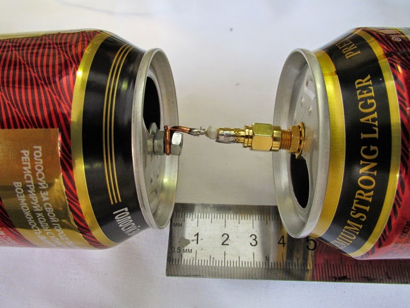
The number of cans can be used differently; it is believed that it is optimal to create 3 or 4 lines of cans, since 1-2 lines pick up the signal weakly, and more than 5 lines are difficult to coordinate. In addition to cans, you need to prepare the following materials:
- About 5 meters of ordinary TV cable marked “RK-75”;
- Wooden or plastic base structure;
- Several self-tapping screws, electrical tape, and a soldering iron.
First you need to prepare the TV cable: step back 10 cm from the edge, make a shallow cut and remove the top layer of insulation. Carefully twist the inner braided screen into a single bundle. On the same side of the cable, remove the plastic insulation and expose the central core. A plug must be connected to the opposite end of the cable.
Next, we will need to connect the coaxial cable to the banks. To do this, it is better to use small flea screws for drywall: screw a twisted cable braid to one can, and a copper core to the second can. For better contact, connections can be soldered.

Now you should secure the cans to a wooden base plate. This can be done using ordinary adhesive tape, electrical tape or a glue gun; you can even use an ordinary clothes hanger or any flat structure at hand. The main thing is that the metal cans are of the same shape, the same size (volume) and are located strictly on the same line. The distance between the sheet metal elements, as well as the location of the antenna installation, is selected experimentally.
You can improve the design by creating a grid of several lines with banks, and if there is such an opportunity, then connect an amplifier. If a homemade antenna made from beer cans is placed on the street, then its elements will have to be hidden in larger plastic bottles.
The length of the cable affects the signal attenuation: the longer the cord, the more the on-air transmission is attenuated. This is especially true for receiving meter waves.
Setting up and searching for channels
Today, digital television offers us as many as 22 television channels in two packages, and in some metropolitan areas there are even more. Setting them up on your TV or set-top box will be quite simple.
In DTV broadcast on 1 frequency, not one channel is broadcast, as it once was on analogue broadcast, but up to 10 channels in one package or multiplex. For example, on frequency 43 you can receive 10 TV channels and 3 radio stations. Therefore, setting up digital broadcasting uses only 2 frequencies. However frequency parameter channels will be different for different areas.

If you are using a home-made antenna in an area with good signal strength, then there are no special recommendations for setting up channels. You simply turn on the function on your TV « Automatic search channels" and the receiver finds all available channels in digital and analogue air.
If the area of your location is not very favorable for TV broadcasting, and the auto search did not produce results, then you need to perform the following steps:
- Check which direction your antenna is facing. It should be turned towards the television tower or directed towards the nearest high-rise building. If you don't know which way the broadcast base is located, pay attention to your neighbors' antennas (but don't look at satellite dishes, which pick up signals from satellites).
- In channel settings, set a restriction: search only for digital channels (or DTV). Well, if you know the frequency parameter, then you can enter the mode manual settings channels, from the remote control dial the number of the channel on which the package is being broadcast, and a signal level scale in percentage should appear on the display. Change the position of the antenna device and see how the stability of this indicator changes.
The change in signal level when rotating the antenna will not change instantly, but after 5-10 seconds. Therefore, pause when changing the position of the catcher.
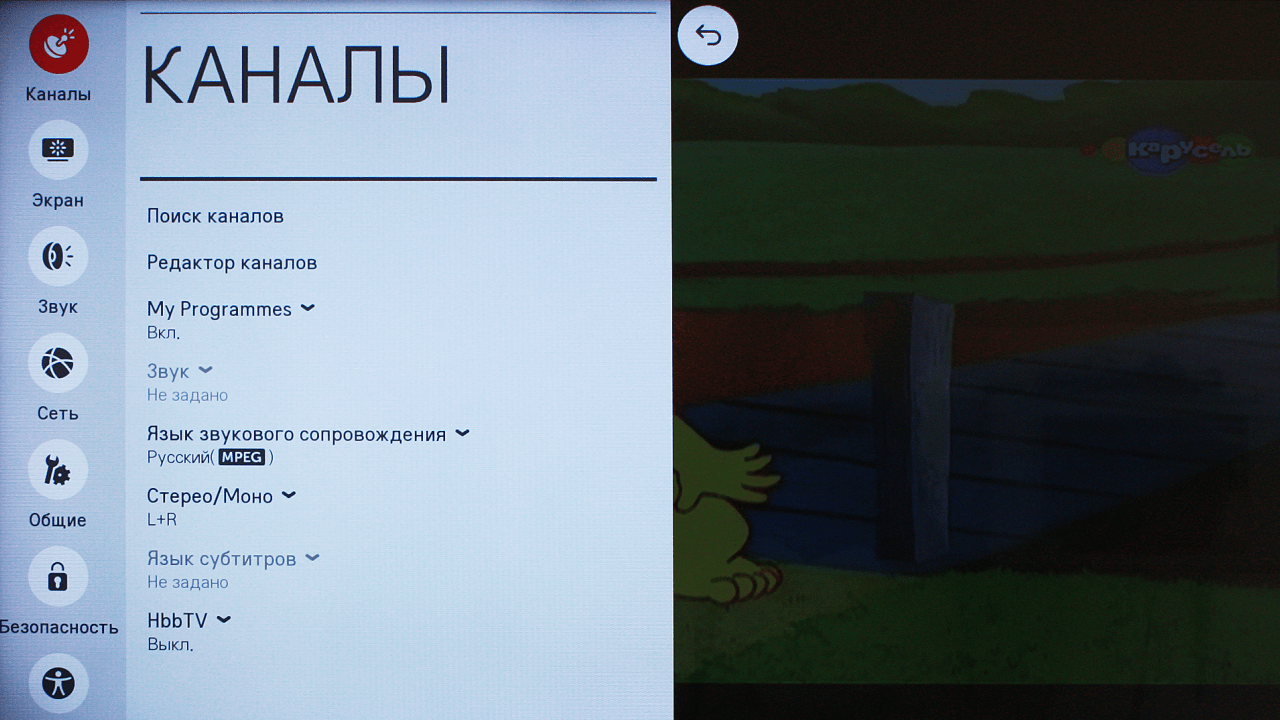
When you get the best signal strength, start scanning for digital channels and save your settings. Perform the same algorithm of actions to search for the second multiplex. If the situation is completely sad and not a single method has yielded results, you may need to make the design of your antenna more powerful or supplement it with an amplifier.


